Ductwork Design: Manual D and Proper Air Distribution
Picture a home where the master bedroom stays ten degrees warmer than the living room in summer, where the furnace runs constantly but never quite keeps up, and where a low, persistent whooshing sound follows you through every hallway. These are not equipment problems. They are ductwork problems. The duct system is the circulatory system of any HVAC installation, responsible for delivering conditioned air to every room and returning stale air back to the equipment for reconditioning. When that system is poorly designed, even the most advanced furnace or air conditioner cannot perform as intended. Manual D, published by the Air Conditioning Contractors of America (ACCA), is the industry-standard methodology for residential duct design. It provides a structured, calculation-based approach to sizing ducts, selecting fittings, and ensuring that every room in a building receives the right volume of air at the right velocity. This article covers the foundational physics of airflow in ducts, walks through the Manual D process step by step, and addresses materials, air distribution principles, and common mistakes that compromise system performance.
Foundational Concepts of Duct Airflow
Before sizing a single duct run, a designer must understand the physical forces at work inside the system. Four interrelated concepts govern how air moves through ductwork.
Static Pressure
Static pressure is the outward force that air exerts on the walls of the duct when at rest or in motion. It is measured in inches of water column (in. w.c.) and serves as the primary indicator of resistance within the system. Residential HVAC systems typically operate within a total external static pressure range of 0.5 to 0.8 in. w.c., though the exact value depends on the equipment manufacturer’s specifications. When static pressure is too high, the blower works harder, consumes more energy, and wears out faster. When it is too low, airflow may be insufficient to condition the space.
Velocity Pressure and Total Pressure
Velocity pressure is the kinetic energy component of air in motion within the duct. It increases with airflow speed and is also measured in inches of water column. Total pressure at any point in the duct system equals the sum of static pressure and velocity pressure. Understanding total pressure allows designers to account for energy losses at every fitting, transition, and length of straight duct in the system.
Airflow in CFM
CFM, or cubic feet per minute, measures the volumetric flow rate of air. Every room in a building has a specific CFM requirement based on its heating and cooling load. If a bedroom needs 6,000 BTU/h of cooling and the system delivers air at a 20-degree temperature differential, the math yields roughly 150 CFM for that room. These room-by-room CFM values, derived from load calculations, are the starting point for all duct sizing.
Friction Rate
Friction rate describes the pressure loss per 100 feet of duct caused by air rubbing against the interior duct walls. Smooth galvanized steel has a lower friction rate than corrugated flexible duct for the same diameter and airflow. Friction rate is a critical variable in duct sizing because it directly determines how large each duct section must be to deliver the required CFM without exceeding the system’s static pressure budget.
Manual D: A Step-by-Step Methodology
Manual D is not simply a duct sizing chart. It is a comprehensive design process that begins with building load data and ends with a verified, balanced system. Each step feeds into the next, and skipping any step introduces error.
Step 1: Start with Manual J Load Calculations
Duct design begins with Manual J, ACCA’s load calculation procedure. Manual J determines the heating and cooling loads for the entire building and for each individual room, expressed in BTU/h. These loads account for insulation levels, window area and orientation, infiltration rates, internal heat gains, and local climate data. Without an accurate Manual J calculation, every downstream decision in the duct design process rests on guesswork.
Step 2: Determine Room-by-Room CFM Requirements
Once Manual J establishes each room’s BTU/h requirement, the designer converts those loads into CFM values. This conversion uses the temperature differential between the supply air and the room air. For cooling, a typical supply air temperature of 55°F against a 75°F room temperature yields a 20-degree delta-T. For heating, the differential is usually larger. The CFM values for all rooms must sum to the total system CFM, which should match the blower capacity of the selected equipment (determined through Manual S, the equipment selection procedure).
Step 3: Design the Duct Layout
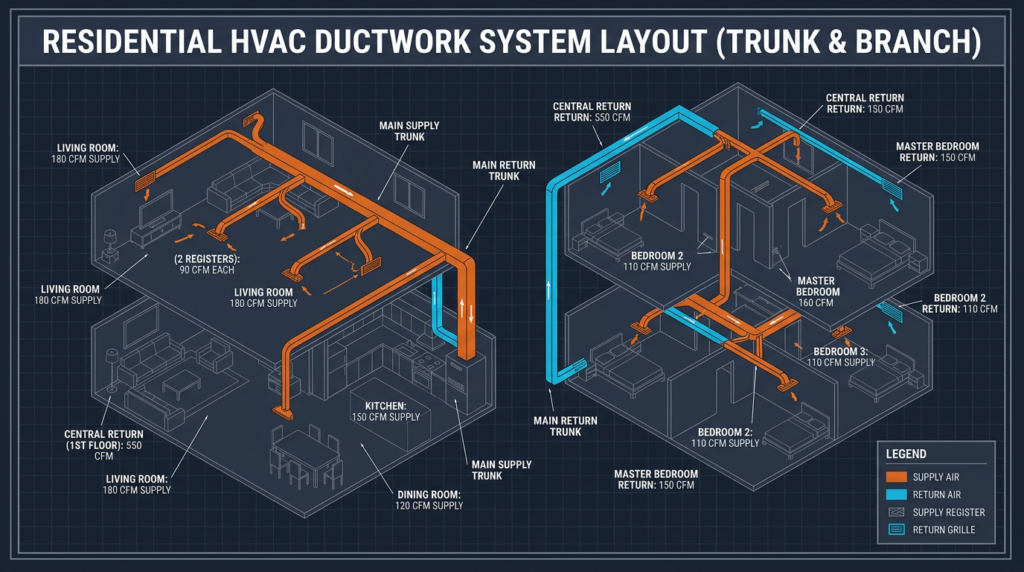
The designer then plans the physical routing of the duct system. Key principles include keeping duct runs as short as possible, minimizing the number of turns and transitions, and maintaining accessibility for future maintenance and cleaning. The layout establishes a hierarchy: a main trunk line carries the full system airflow from the air handler, and smaller branch ducts peel off to serve individual rooms or groups of rooms. Trunk lines may reduce in size as branches take away airflow, a technique called trunk reduction.
Step 4: Establish a Static Pressure Budget
The static pressure budget allocates the equipment’s available external static pressure across all components of the duct system. This budget must account for the supply side, the return side, and all accessories such as filters, coils, dampers, and grilles. For example, if the air handler is rated for 0.5 in. w.c. of external static pressure and the filter and coil together consume 0.20 in. w.c., only 0.30 in. w.c. remains for the supply and return ductwork combined. The designer must size every duct section to stay within this remaining budget.
Step 5: Size the Ducts
With CFM values and the friction rate budget established, the designer uses Manual D’s sizing tables or duct calculators to determine the diameter (for round ducts) or dimensions (for rectangular ducts) of each section. Two primary methods exist:
- Equal friction method: The most common residential approach. Every section of ductwork is sized to produce the same friction rate per 100 feet, ensuring a predictable and uniform pressure drop throughout the system.
- Static regain method: Used more often in commercial applications, this method sizes ducts so that the static pressure regained from velocity reduction at each branch takeoff offsets the friction loss in the next duct section, maintaining nearly constant static pressure throughout the trunk.
General velocity guidelines for residential systems include 700 to 900 feet per minute (fpm) in main trunk lines, 500 to 700 fpm in branch ducts, and 300 to 500 fpm at registers. Exceeding these ranges creates audible noise; falling well below them wastes material and can impair air mixing.
Step 6: Select Fittings and Calculate Equivalent Lengths
Every elbow, tee, transition, and takeoff fitting introduces additional pressure loss beyond what straight duct creates. Manual D provides fitting equivalent length tables that express each fitting’s resistance as an equivalent length of straight duct. A sharp 90-degree elbow, for instance, might have an equivalent length of 40 feet, while a long-radius elbow might be only 10 feet. Selecting low-loss fittings and accounting for their resistance in the pressure budget is essential to keeping the system within its design parameters.
Step 7: Verify System Performance
After installation, the system must be tested. A technician uses a manometer to measure static pressure at the air handler and at key points throughout the duct system, and an anemometer or flow hood to measure CFM at each register. Temperature differentials between supply and return air confirm that the equipment is operating correctly. If measured values deviate from the design, adjustments to dampers, register settings, or duct connections are required.
Software Tools
While Manual D calculations can be performed by hand, most professionals use software such as Wrightsoft Right-D or Elite Software Ductsize. These programs automate friction rate calculations, fitting selections, and pressure budget tracking, reducing errors and accelerating the design process.
Air Distribution Principles
Getting the right CFM to each room is only half the challenge. How that air enters and circulates within the room determines whether occupants feel comfortable or drafty.
Throw, Spread, and Drop
Throw is the distance conditioned air travels from a supply diffuser before its velocity drops to a terminal value, typically 50 fpm. A diffuser with too little throw leaves the far side of the room unconditioned. Too much throw bounces air off the opposite wall and creates drafts. Spread describes the width of the airstream pattern. Drop refers to how far the air falls vertically due to gravity and temperature differences, a factor especially important with ceiling-mounted diffusers delivering cool air.
Diffuser and Register Selection
Different supply outlets suit different applications. Ceiling diffusers with radial throw work well in rooms with standard ceiling heights. Linear slot diffusers provide uniform coverage along walls of windows. Floor registers with adjustable louvers direct air upward along exterior walls to counteract cold drafts in heating-dominant climates. The key is matching the diffuser’s rated throw and spread to the room’s geometry and airflow volume.
Return Air Placement
Proper return air placement ensures that conditioned air circulates fully before being drawn back to the air handler. In cooling-dominant climates, high return grilles capture warm air near the ceiling. In heating-dominant climates, low returns collect cooler air near the floor. Every room with a supply register needs a return air pathway, whether through a dedicated return duct, a transfer grille, or an adequately undercut door. Without this pathway, closing a bedroom door creates positive pressure that forces conditioned air out through gaps and cracks, wasting energy and starving the return side of the system.
Balancing Dampers
Balancing dampers installed in branch ducts allow fine-tuning of airflow to individual rooms. After installation, a technician adjusts these dampers to match measured CFM to design CFM at each register, a process called air balancing.
Duct Materials and Construction
Metal Ductwork
Galvanized steel is the gold standard for duct construction. It offers low friction loss, excellent durability, and resistance to mold growth. Aluminum is lighter and resistant to corrosion. Metal duct costs more to fabricate and install but delivers the best long-term performance.
Flexible Ductwork
Flex duct is inexpensive and easy to install, making it popular for branch runs. However, its corrugated inner liner creates significantly higher friction losses than smooth metal, sometimes two to three times greater for the same diameter. Flex duct must be pulled taut, supported at proper intervals (typically every 4 to 5 feet), and kept to short runs. Kinks, sags, and excessive lengths are among the most common causes of poor system performance in residential installations.
Duct Board
Fiberglass duct board provides built-in insulation and sound attenuation. It is lighter than metal and moderately priced. However, it requires careful installation to prevent moisture intrusion and potential mold growth on the fiberglass surface. Its lower durability makes it less suitable for exposed or high-traffic mechanical rooms.
Sealing and Insulation
Duct sealing is arguably the single highest-impact quality measure in any duct system. The U.S. Department of Energy estimates that typical duct systems lose 25 to 40 percent of conditioned air through leaks. All joints and seams should be sealed with mastic or UL 181-rated foil tape. Aeroseal technology, which injects aerosolized sealant particles into pressurized ductwork to seal leaks from the inside, has emerged as an effective solution for both new and existing systems. All ducts running through unconditioned spaces such as attics, crawlspaces, and garages must be insulated. Required insulation R-values vary by climate zone, with most codes calling for R-6 to R-8 on supply ducts in unconditioned spaces.
Common Misconceptions and Pitfalls
- “Bigger ducts are always better.” Oversized ducts reduce air velocity, which impairs mixing at the register and can cause cold dumping from ceiling diffusers. Proper sizing based on Manual D calculations always outperforms guesswork.
- Skipping Manual D entirely. Many contractors size ducts by rule of thumb or experience. This leads to pressure imbalances, comfort complaints, and equipment that cycles inefficiently.
- Sloppy flex duct installation. A 6-inch flex duct that is kinked or compressed to a 4-inch effective diameter delivers a fraction of its rated airflow. Installation quality matters as much as material selection.
- Ignoring duct leakage. Unsealed ducts in an attic can waste hundreds of dollars per year in energy costs while pulling contaminants into the airstream.
- Treating all registers as interchangeable. A register rated for 100 CFM with a 6-foot throw is not equivalent to one rated for 100 CFM with a 12-foot throw. Room geometry dictates register selection.
- Forgetting return air pathways. Closed doors without transfer grilles or jump ducts create pressure imbalances that reduce system efficiency by 5 to 15 percent.
Practical Applications
In new construction, Manual D allows builders to integrate duct routing into the framing plan, minimizing the number of ducts in unconditioned spaces and optimizing run lengths. In retrofit applications, a Manual D analysis of an existing system often reveals undersized returns, excessive flex duct lengths, or trunk lines that were never reduced, all of which can be corrected to dramatically improve comfort and efficiency. For homes with zoning systems, Manual D is essential to ensure that each zone receives adequate airflow when other zones are closed, preventing dangerous static pressure spikes that can damage equipment.
Current Standards and Emerging Trends
The 2021 International Energy Conservation Code (IECC) and subsequent updates have tightened requirements for duct leakage testing, with many jurisdictions now requiring total leakage rates below 4 CFM per 100 square feet of conditioned floor area. ASHRAE continues to refine its standards for duct construction and sealing. The Inflation Reduction Act (IRA), signed into law in 2022, provides rebates and tax credits for energy-efficient HVAC upgrades, including duct sealing and insulation improvements, through programs like the Home Efficiency Rebate program. Advanced building enclosure strategies and the push toward electrification with heat pumps are making proper duct design even more critical, as heat pumps operate at lower supply air temperatures and are more sensitive to airflow restrictions than traditional furnaces.
Key Takeaways
- Manual D is the ACCA standard for residential duct design and should be followed for every new installation and major renovation.
- Accurate Manual J load calculations are the essential foundation for all duct sizing decisions.
- The static pressure budget governs every sizing choice. Exceeding the equipment’s rated external static pressure reduces efficiency and shortens equipment life.
- Duct material selection, fitting quality, and installation practices all affect friction losses and system performance.
- Seal all duct joints with mastic or approved tape. Duct leakage is the single largest source of energy waste in most residential HVAC systems.
- Proper air distribution depends on matching diffuser throw, spread, and drop characteristics to each room’s size and layout.
- Always verify system performance after installation with static pressure and airflow measurements.
- Consult a qualified HVAC professional who follows ACCA Manual D procedures. The long-term savings in energy costs, equipment life, and occupant comfort far outweigh the upfront investment in proper duct design.