Thermostat Wiring: Complete Guide for Every System Type
You have just unboxed a sleek new smart thermostat, pulled the old unit off the wall, and now you are staring at a tangle of colored wires with no idea which one goes where. This moment of confusion is one of the most common experiences in home HVAC work, and it stops thousands of homeowners in their tracks every year. Thermostat wiring does not have to be intimidating. Once you understand the color codes, terminal designations, and how different HVAC system types are configured, the process becomes logical and manageable. This guide covers everything from basic wire designations and conventional system wiring to heat pump configurations, smart thermostat considerations, and troubleshooting common problems. A critical disclaimer before we begin: this article is for informational purposes only. Always turn off power at the breaker before touching any wiring. High-voltage systems (120V/240V) should only be handled by a qualified electrician, and if you encounter unfamiliar wiring or have any doubts, call a licensed HVAC technician. Safety always comes first.
Key Concepts and Terminology
What a Thermostat Actually Does
A thermostat is a control device that acts as a switch between your living space and your HVAC equipment. When the temperature in your home drifts above or below your set point, the thermostat sends a signal through its wiring to activate the appropriate component, whether that is your furnace, air conditioner, heat pump, or fan. It does not generate heating or cooling on its own. It simply tells the equipment when to turn on and off.
Understanding Voltage
Most residential thermostats operate on low voltage (24VAC), supplied by a transformer located at or inside the furnace or air handler. This low voltage makes basic thermostat work relatively safe for homeowners. However, some systems, particularly electric baseboard heaters, use high-voltage thermostats (120V or 240V) wired directly into the electrical circuit. These carry the same danger as any household electrical wiring and require a qualified electrician for installation or replacement. If you open your thermostat and see thick wires connected to terminals labeled L1 and L2 instead of the typical thin colored wires, stop immediately and call a professional.
Common Wire Designations
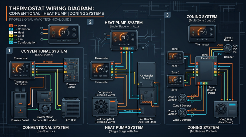
Thermostat wiring follows a standardized color and letter coding system. While wire colors can occasionally vary from one installer to another, the terminal letter designations on the thermostat and the equipment are consistent. Here are the standard designations:
- R (Red) — Power: Carries 24VAC power from the transformer. On some thermostats, this splits into Rc (power for cooling) and Rh (power for heating) when separate transformers are used. If your system has a single transformer, a jumper wire bridges Rc and Rh together.
- C (Blue/Common) — Common Wire: Provides the return path for 24VAC power, completing the circuit. Not all older systems have a C-wire run to the thermostat, but it is increasingly important for smart thermostats that need continuous power.
- W (White) — Heat: Signals the heating system to activate. In multi-stage systems, W1 is first-stage heat and W2 is second-stage or auxiliary heat.
- Y (Yellow) — Cooling: Signals the air conditioner or heat pump to provide cooling. Y1 is first-stage cooling; Y2 is second-stage cooling.
- G (Green) — Fan: Controls the indoor blower fan independently of heating or cooling.
- O/B (Orange or Blue) — Reversing Valve: Used exclusively in heat pump systems. The O terminal energizes the reversing valve in cooling mode (most common, used by brands like Carrier, Trane, and Lennox). The B terminal energizes it in heating mode (used primarily by Rheem and Ruud). Properly identifying this wire is critical to correct heat pump operation.
- E — Emergency Heat: Activates backup heating in heat pump systems, bypassing the heat pump entirely.
- Aux — Auxiliary Heat: Engages a supplemental heat source (usually electric resistance strips) to assist the heat pump during extremely cold conditions.
- L — Fault Indicator: Communicates equipment fault codes to certain thermostats.
Wire gauge for thermostat cabling is typically 18 to 22 gauge, bundled in a jacket containing anywhere from two to eight individual conductors. The most common cable for modern systems is 18/5 (five conductors of 18-gauge wire) or 18/8 for more complex setups.
Before disconnecting any wires from an old thermostat, take a clear photograph of the wiring and label each wire with tape noting which terminal it was connected to. This single step prevents the majority of wiring mistakes during thermostat replacement.
Wiring Configurations by System Type
Conventional Forced-Air Systems
Conventional systems use a furnace for heating and a separate air conditioner for cooling. The wiring is straightforward because each wire controls a distinct function.
Heating only systems require just two wires:
- R — Power (24VAC)
- W — Heat call
Cooling only systems typically use three wires:
- R — Power
- Y — Cooling call
- G — Fan
Combined heating and cooling systems use four or five wires:
- R (or Rc/Rh with jumper) — Power
- W — Heat
- Y — Cooling
- G — Fan
- C — Common (if available)
The G wire is important in these systems because it allows the thermostat to run the indoor fan independently, which is useful for air circulation without active heating or cooling. On the thermostat side, if you see separate Rc and Rh terminals and your system uses a single transformer, install the jumper that comes with most thermostats or connect R to both terminals.
Heat Pump Systems
Heat pumps move refrigerant in two directions, providing both heating and cooling from a single outdoor unit. This reversibility introduces the O/B wire, which controls a reversing valve that determines the direction of refrigerant flow.
Heat pump with auxiliary/emergency heat (the most common configuration):
- R — Power
- Y — Compressor (cooling and heating via the heat pump)
- G — Fan
- O or B — Reversing valve
- W or Aux — Auxiliary heat (electric strip heat)
- E — Emergency heat
- C — Common (recommended)
Heat pump without auxiliary heat (less common, typically in mild climates):
- R — Power
- Y — Compressor
- G — Fan
- O or B — Reversing valve
- C — Common
The reversing valve is the key component that makes a heat pump work in both modes. When wired to the O terminal, the valve energizes during cooling mode, which is the default for most major manufacturers. When wired to B, it energizes during heating mode. Getting this wrong will cause the system to cool when it should heat and vice versa. Always verify with your equipment documentation.
Multi-Stage Systems
Multi-stage systems offer variable output levels for greater comfort and efficiency. They use additional wires to control each stage.
Two-stage heating adds a W2 wire to signal the second stage, which fires when the first stage cannot meet demand. A typical configuration includes R, W1, W2, Y, G, and C.
Two-stage cooling adds a Y2 wire for the second compressor stage. Configuration: R, Y1, Y2, W, G, and C.
The thermostat determines when to engage the second stage based on how quickly the home is reaching the set temperature. If progress is too slow, it activates the additional stage for more output.
High-Voltage Systems
Warning: High-voltage thermostat systems operate at 120V or 240V and pose a serious risk of electrical shock or fire. Only a qualified electrician should work on these systems.
Electric baseboard heaters are the most common high-voltage application. They use line-voltage thermostats wired with thick-gauge cable to terminals labeled L1 and L2. These thermostats look and function differently from low-voltage models, and standard smart thermostats are not compatible without specialized line-voltage smart models designed for this purpose.
Zone Control Systems
Zone control systems use multiple thermostats connected to a central control panel that operates motorized dampers within the ductwork. Each zone has its own thermostat, and the control panel coordinates signals to the HVAC equipment. The wiring between each thermostat and the zone panel follows standard conventions, but the panel-to-equipment wiring is significantly more complex. Installation and troubleshooting of zone systems should be left to professionals.
Millivolt Systems
Millivolt systems are commonly found in older gas fireplaces, wall heaters, and some floor furnaces. They generate their own small electrical current (typically 250 to 750 millivolts) from a thermocouple or thermopile heated by a pilot flame. They do not use 24VAC transformers and require compatible millivolt thermostats. Standard digital and smart thermostats will not work with these systems without an adapter relay.
Smart Thermostat Wiring and Considerations
Smart thermostats from manufacturers like Ecobee, Google Nest, and Honeywell Home offer energy savings of 10 to 23 percent according to EPA estimates, along with remote control via smartphone apps, learning algorithms, geofencing, and voice assistant integration. However, they have specific wiring requirements that older systems may not satisfy out of the box.
The C-Wire Requirement
Most smart thermostats require a dedicated C-wire to provide continuous 24VAC power for their Wi-Fi radios, displays, and processors. Unlike older mechanical thermostats that operated on almost no electricity, smart thermostats draw steady power. As of 2024, manufacturers increasingly recommend a hardwired C-wire connection for reliable performance, moving away from earlier workarounds.
C-Wire Adapters
If your existing thermostat cable does not include a C-wire, a C-wire adapter (also called an add-a-wire kit) offers one solution. These devices install at the furnace or air handler and repurpose an existing wire, typically splitting the G (fan) signal to create a common connection. The adapter then manages fan control through the repurposed wiring. Brands like Venstar and Ecobee offer adapter kits. However, adapters are not compatible with all systems, particularly heat pumps with complex wiring, so check compatibility before purchasing.
Power-Stealing Thermostats
Some smart thermostats, notably certain Nest models, use a technique called power stealing, where the thermostat draws a small amount of current through the R and other active wires even when the system is off. While this eliminates the need for a C-wire in theory, it can cause problems with certain furnaces, including short cycling, relay clicking, and erratic behavior. Furnaces with electronic control boards are particularly sensitive to power stealing. If you experience these issues, adding a C-wire or adapter is the recommended fix.
Wireless Thermostats
Wireless thermostat systems use a base unit or receiver wired to the HVAC equipment with a wirelessly communicating thermostat that can be placed anywhere in the home. This approach is useful for homes where running new thermostat cable is impractical. The base unit handles all physical wiring connections, while the thermostat communicates via radio frequency or Wi-Fi. Battery life and signal range are the primary limitations.
Compatibility Checks
Before purchasing any smart thermostat, use the manufacturer’s online compatibility checker. You will need to identify the wires currently connected at your thermostat. These tools confirm whether your system type and wiring support the thermostat you want. Skipping this step is a common and costly mistake.
Troubleshooting Common Wiring Issues
No Power to the Thermostat
- Check the HVAC circuit breaker and reset if tripped.
- Inspect the 24VAC transformer for output using a multimeter set to AC voltage. A reading significantly below 24V indicates a failing transformer.
- Check for loose wire connections at both the thermostat and the equipment terminals.
- Look for a blown fuse on the furnace control board (commonly a 3-amp or 5-amp automotive-style fuse).
System Not Responding to Heat or Cool Calls
- Verify wires are connected to the correct terminals on the new thermostat.
- Confirm thermostat is set to the correct mode (heat, cool, or auto).
- Check for a tripped high-limit safety switch on the furnace.
- Verify the system type is correctly configured in the thermostat settings (conventional vs. heat pump).
Fan Running Constantly
- Check if the thermostat fan setting is on “On” instead of “Auto.”
- Verify the G wire is connected to the G terminal and not shorted to R.
Heating and Cooling Running Simultaneously or Reversed
- The O/B wire is likely configured incorrectly. Switch the O/B setting in your thermostat’s system configuration.
- Verify the reversing valve wire is on the correct terminal.
Short Cycling
- Check for a wiring short, where bare wire ends touch each other or the mounting plate.
- Verify the thermostat is not located near a heat source, supply vent, or in direct sunlight, which causes false temperature readings.
- On smart thermostats without a C-wire, power stealing may cause short cycling. Add a C-wire or adapter.
Using a Multimeter Safely
A multimeter is the single most useful tool for thermostat wiring troubleshooting. Set it to AC voltage to test for 24VAC between R and C at the thermostat location. Set it to continuity mode to verify wires are not broken between the thermostat and the equipment. Always confirm the HVAC breaker is off before touching wire connections, and turn it back on only when testing for voltage with meter probes in place. Never touch bare wire ends with your fingers while power is on, even at 24V.
Safety Precautions
- Turn off power at the circuit breaker before removing or connecting any thermostat wiring. Verify the power is off with a multimeter or voltage tester.
- Never work on high-voltage systems (120V/240V) unless you are a qualified electrician.
- Use insulated tools rated for electrical work.
- Label and photograph all wires before disconnecting them from the old thermostat.
- If wiring does not match standard colors, if you find more wires than expected, or if anything looks unfamiliar, stop and call a licensed HVAC technician.
Key Takeaways
Thermostat wiring follows a logical system of color-coded, letter-designated wires that correspond to specific HVAC functions. Conventional heating and cooling systems use the simplest configurations with R, W, Y, and G wires. Heat pump systems add the O/B reversing valve wire and often auxiliary or emergency heat connections. Smart thermostats typically require a C-wire for reliable operation, and solutions exist for homes that lack one. Always photograph and label your existing wiring before making any changes, verify compatibility before purchasing a new thermostat, and use a multimeter to diagnose problems methodically. Most importantly, recognize when a job exceeds your comfort level. A qualified HVAC technician can resolve complex wiring issues safely and correctly, and calling one is always the right decision when you are unsure.