A homeowner calls complaining about hot spots upstairs, weak airflow from the vents, and a system that never seems to stop running. The technician arrives, pulls out a manometer, and within minutes identifies the root cause: the system is operating at nearly double its rated static pressure. This scenario plays out thousands of times daily across the industry, and it underscores why understanding static pressure is fundamental to HVAC diagnostics. Static pressure problems silently degrade system performance, drive up energy costs, accelerate equipment wear, and compromise indoor comfort. This article covers the principles of static pressure, how to measure it accurately, what causes abnormal readings, and the practical solutions that restore proper system operation.
Understanding Static Pressure
Static pressure is the resistance to airflow within an HVAC system. Think of it as the force the blower motor must overcome to push conditioned air through the ductwork and pull return air back. It is not air velocity or volume. Instead, it is the outward force air exerts in all directions against duct walls, filters, coils, and other components as it moves through the system. Every component in the airflow path adds resistance, and static pressure is the cumulative measurement of that resistance.
Units of Measurement
In the United States, static pressure is measured in inches of water column (in. w.c.). This unit describes the height to which the pressure differential can push a column of water in a manometer tube. Internationally, Pascals (Pa) are more common. For conversion: 1 in. w.c. equals approximately 249 Pa, and 1 Pa equals roughly 0.004 in. w.c. Most residential and light commercial work in the US uses in. w.c. exclusively.
Total Static Pressure vs. External Static Pressure
Total static pressure (TSP) is the sum of the positive (supply side) and negative (return side) static pressure readings taken at the air handler. For example, if the supply plenum reads +0.30 in. w.c. and the return plenum reads -0.25 in. w.c., the TSP is 0.55 in. w.c. A balanced system operates at or below its design TSP.
External static pressure (ESP) is the resistance created by everything outside the air handler cabinet, including ductwork, grilles, registers, dampers, and accessories like UV lights or humidifiers. ESP is the measurement technicians rely on most often to diagnose ductwork and distribution problems. Manufacturers rate their equipment to deliver a specified airflow (measured in CFM) at a specific maximum ESP. This rating appears on the equipment nameplate and in the installation manual.
Design Static Pressure
Every HVAC system is designed to operate within a specific static pressure range. Most residential systems are rated for a maximum ESP of 0.50 in. w.c., though some high-efficiency units are rated at 0.20 to 0.30 in. w.c. When actual operating static pressure exceeds the design specification, airflow drops, efficiency suffers, and equipment life shortens. The manufacturer’s installation manual is the authoritative source for the correct design static pressure for any given unit.
The core relationship is straightforward: as static pressure increases, airflow decreases. A system rated for 400 CFM per ton at 0.50 in. w.c. ESP might deliver only 300 CFM per ton at 0.80 in. w.c. That 25% reduction in airflow has serious consequences for performance and comfort.
Why Proper Static Pressure Matters
Operating outside the design static pressure range affects virtually every aspect of system performance:
- Energy efficiency: When static pressure is too high, the blower motor works harder to push air through the system. ECM motors compensate by ramping up wattage, and PSC motors simply deliver less air. Either way, energy consumption rises while delivered comfort drops. Studies from the US Department of Energy suggest that duct-related losses account for 25% to 40% of total HVAC energy use in a typical home.
- Comfort: Reduced airflow leads to uneven temperatures, hot and cold spots, and longer run cycles. Rooms far from the air handler suffer most because pressure losses compound over distance.
- Equipment lifespan: High static pressure forces the blower motor to operate under excessive load, generating heat that degrades motor windings and bearings. Compressors can also suffer because low airflow across the evaporator coil causes the suction pressure to drop, potentially leading to liquid slugging or compressor overheating. These conditions can cut equipment life by 30% to 50%.
- Indoor air quality: Poor airflow reduces filtration effectiveness. Air bypasses the filter through gaps, and pollutants circulate rather than being captured. Low airflow across the evaporator coil can also cause the coil to freeze, leading to moisture problems and potential mold growth.
- Noise: High static pressure creates turbulence, especially at fittings, transitions, and registers. The result is whistling, rumbling, and rushing noises that homeowners find unacceptable.
Measuring Static Pressure
Tools Required
- Manometer: A digital manometer is the standard instrument for measuring static pressure. Models from manufacturers like Fieldpiece, Testo, and Dwyer are common in the trade. Digital manometers offer accuracy to 0.01 in. w.c. or better. Analog (inclined) manometers still work but are less practical in the field. Calibration should be verified regularly by zeroing the instrument before each use.
- Static pressure tips (probes): These small metal tubes insert into test holes drilled in the ductwork or plenum. The probe must be oriented perpendicular to airflow so it reads only static pressure, not velocity pressure. Do not confuse static pressure probes with pitot tubes, which are designed to measure velocity pressure.
- Drill or punch: A 3/8-inch drill bit or sheet metal punch creates the test port. Some technicians use a self-piercing tip for speed.
- Sealing material: Use foil tape, duct putty, or magnetic plugs to seal test holes after measurements are complete.
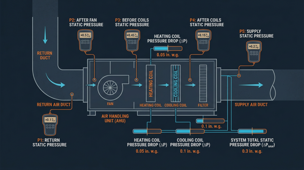
Measurement Points
The two primary measurement points for determining TSP are in the supply plenum (after the air handler) and the return plenum (before the air handler). Drill test ports at least 18 inches downstream of the supply connection and 18 inches upstream of the return connection to avoid turbulence near the unit.
For component-level diagnosis, take additional readings before and after the air filter, before and after the evaporator coil, and at key points along duct runs. The difference between readings on either side of a component is the pressure drop across that component. For example, a clean 2-inch MERV 8 filter typically has a pressure drop of 0.05 to 0.10 in. w.c. A dirty MERV 13 filter might read 0.30 in. w.c. or higher.
Measurement Procedure
- Set the system to operate in the mode you intend to test (cooling, heating, or fan only). Allow the system to run for several minutes to reach steady-state operation.
- Zero the manometer with both ports open to atmospheric pressure.
- Insert the static pressure probe into the supply plenum test port. Connect the probe tubing to the positive (+) port on the manometer. Record the reading.
- Move the probe to the return plenum test port. Connect the tubing to the negative (-) port on the manometer. Record the reading.
- Add the absolute values of both readings to calculate TSP. For example, a supply reading of +0.35 in. w.c. and a return reading of -0.30 in. w.c. gives a TSP of 0.65 in. w.c.
- Compare the TSP to the manufacturer’s rated ESP. If the TSP exceeds the rated ESP, the system has excessive static pressure and further diagnosis is needed.
- Seal all test ports with foil tape or plugs when finished.
Interpreting Readings
For most residential systems, a TSP of 0.50 in. w.c. or less is acceptable. Commercial systems vary widely based on design. If the measured TSP is more than 0.10 in. w.c. above the manufacturer’s rated ESP, investigate the cause. Pressure drop readings across individual components help pinpoint where the excess resistance exists. A clean evaporator coil typically adds 0.10 to 0.25 in. w.c. A dirty coil can add 0.40 in. w.c. or more.
Diagnosing High Static Pressure
Common Causes
- Dirty air filter: This is the single most common cause of high static pressure. A clogged filter can add 0.20 to 0.50 in. w.c. of resistance. Filters should be inspected monthly and replaced per the manufacturer’s schedule, typically every 30 to 90 days for standard 1-inch filters and every 6 to 12 months for 4- to 5-inch media filters.
- Undersized ductwork: Ducts that are too small for the required airflow create excessive resistance. This is a design deficiency that requires duct modification or replacement. ACCA Manual D provides the industry standard for duct sizing calculations.
- Collapsed or crushed flex duct: Flex duct that is kinked, compressed against framing, or sagging excessively can lose a significant portion of its effective cross-sectional area.
- Dirty evaporator coil: Dust and debris accumulate on the coil over time, restricting airflow. Annual coil cleaning is recommended as part of routine maintenance.
- Closed or blocked registers: Closing supply registers does not save energy. It increases static pressure and forces the blower to work harder. Even furniture placed over return grilles can cause measurable increases in resistance.
- Excessive fittings and sharp turns: Every elbow, tee, and transition adds resistance. Ductwork with numerous sharp 90-degree turns and poorly designed fittings can accumulate substantial pressure losses.
- Malfunctioning zone dampers: In zoned systems, a stuck-closed damper or an improperly programmed zone control board can restrict airflow to a significant portion of the system.
- Incorrect blower speed: A blower speed set too high for the duct system will create excessive static pressure. This is particularly common after equipment replacement when the installer does not verify airflow against the duct capacity.
Troubleshooting Techniques
Start with a visual inspection: check the filter, look for crushed ducts in accessible areas, verify that all registers are open, and inspect the evaporator coil. Measure the pressure drop across the filter and coil individually. If the filter accounts for more than 0.20 in. w.c. of the total, replace it and retest. Use an airflow hood or anemometer at supply registers to verify delivered CFM. Compare the total measured supply airflow to the system’s rated CFM. A significant deficit confirms that the high static pressure is reducing air delivery.
Current energy codes, including the 2024 IECC and recent state amendments, increasingly require duct leakage testing on new construction and major renovations. While duct leakage technically reduces static pressure in some areas, it starves downstream runs and can cause localized high-pressure conditions upstream of the leak points.
Diagnosing Low Static Pressure
Common Causes
- Oversized ductwork: Ducts that are too large for the airflow volume result in low velocity and low static pressure. While this may sound beneficial, low-velocity air fails to mix properly, leading to stratification, poor temperature distribution, and occupant discomfort.
- Significant duct leakage: Large gaps, disconnected sections, or unsealed joints bleed conditioned air into unconditioned spaces, reducing system resistance and wasting energy.
- Blower motor failure: A failing motor or a motor with a bad capacitor may not generate enough airflow to create normal operating pressures.
- Incorrect blower speed: A speed setting that is too low produces insufficient airflow and abnormally low static pressure readings.
- Open or disconnected ducts: A supply or return duct that has separated at a joint or boot creates a massive air leak, effectively short-circuiting the system.
Troubleshooting Techniques
Inspect the ductwork for visible disconnections, especially in attics, crawlspaces, and basements where ducts are subject to physical disturbance. Use a smoke pencil at joints and connections to detect leaks. Verify blower motor operation by checking amp draw against the motor’s rated full load amps (FLA). Confirm the blower speed setting matches the equipment manufacturer’s recommendation for the installed duct system.
Solutions for Static Pressure Problems
- Filter replacement and selection: Replace dirty filters promptly. Choose filters with an appropriate MERV rating for the system. Most residential systems perform well with MERV 8 to MERV 11 filters. MERV 13 and higher filters may cause excessive pressure drop unless the system is designed to accommodate them. Higher-MERV filters require more surface area, so upgrading to a 4- or 5-inch deep-pleated filter cabinet is often the best approach.
- Duct sealing: Seal all accessible duct joints with mastic sealant or UL 181-rated tape. For inaccessible ducts, aerosol-based duct sealing (such as Aeroseal) can reduce leakage from the inside. Proper duct sealing alone can improve system efficiency by 15% to 30%.
- Duct repair and modification: Replace crushed or damaged sections. Straighten flex duct runs and support them at intervals no greater than 4 feet. Replace sharp 90-degree hard turns with swept elbows or turning vanes. If the duct system is fundamentally undersized, adding trunk lines or increasing branch duct diameters is necessary. All duct sizing changes should follow ACCA Manual D guidelines.
- Evaporator coil cleaning: Clean the coil annually using a no-rinse foaming cleaner or a coil cleaning solution appropriate for the coil type. Ensure the condensate drain is clear after cleaning.
- Blower motor adjustment: For PSC motors, adjust the speed tap to achieve the target airflow at or below the rated ESP. For ECM motors, verify the programmed airflow setting matches the system requirements. Always measure static pressure and airflow after any speed change.
- Register and damper correction: Open all supply registers fully. Verify that manual balancing dampers are set correctly. In zoned systems, inspect damper actuators and control boards to ensure they respond properly to thermostat calls.
- System redesign: When the existing duct system cannot be repaired or modified to operate within acceptable parameters, a complete duct redesign by a qualified HVAC engineer is the final solution. This is common in older homes where the original ductwork was never engineered for the current equipment.
Common Misconceptions about Static Pressure
- Static pressure equals airflow. It does not. Static pressure is resistance. Two systems can have identical static pressure readings but very different airflow rates depending on blower capacity and duct configuration.
- Higher static pressure means the system is working harder and performing better. The opposite is true. Higher static pressure means the system is fighting more resistance, delivering less air, and consuming more energy.
- Closing vents in unused rooms saves energy. Closing vents increases static pressure, reduces total system airflow, and forces the blower to work against greater resistance. It saves no energy and can damage equipment.
- Any filter will work as long as it fits. A MERV 16 filter installed in a system designed for MERV 8 can add enough resistance to reduce airflow by 20% or more. Filter selection must account for the system’s static pressure budget.
- Bigger ducts are always better. Oversized ducts reduce air velocity, causing poor mixing, temperature stratification, and potential condensation issues in humid climates.
Practical Case Studies
Case 1: High static pressure in a residential system. A two-story home with a 3-ton system showed a TSP of 0.92 in. w.c. against a rated ESP of 0.50 in. w.c. The homeowner reported weak airflow and the system running constantly. Investigation revealed a clogged MERV 13 filter (pressure drop of 0.38 in. w.c.) and a dirty evaporator coil (pressure drop of 0.35 in. w.c.). Replacing the filter with a clean MERV 8 and cleaning the evaporator coil brought the TSP down to 0.42 in. w.c. Airflow increased from 280 CFM per ton to 390 CFM per ton, and the comfort complaints resolved.
Case 2: Low static pressure in a commercial office. A small office suite served by a 5-ton rooftop unit had persistent hot spots and a TSP reading of only 0.18 in. w.c. Inspection of the duct system in the ceiling plenum revealed two fully disconnected flex duct runs and multiple unsealed joints at branch takeoffs. Reconnecting the ducts and sealing all joints with mastic raised the TSP to 0.44 in. w.c. and restored proper air distribution throughout the space.
Related Topics
Static pressure diagnosis connects directly to several other HVAC disciplines. Airflow measurement using anemometers and flow hoods complements static pressure readings by quantifying the actual volume of air delivered. Duct design per ACCA Manual D establishes the framework for achieving correct static pressure from the start. Filter selection based on MERV ratings determines how much of the static pressure budget the filter consumes. System balancing ensures that airflow is distributed correctly across all zones and rooms. And underlying all of these is the heat load calculation (ACCA Manual J), which determines the correct equipment size and airflow requirement that drives every other design decision.
Key Takeaways
Static pressure is the single most informative diagnostic measurement a technician can take in the field. It reveals whether the duct system, filter, coil, and blower are working together as designed or fighting each other. Measure TSP at every service call and compare it to the manufacturer’s rated ESP. Investigate any reading that exceeds the specification by more than 0.10 in. w.c. Address the most common causes first: dirty filters, restricted ducts, and fouled coils. When these simple fixes do not resolve the problem, measure pressure drops across individual components to isolate the source of excess resistance. Proper static pressure management keeps systems efficient, quiet, and reliable for their full expected service life. When in doubt, consult with a qualified HVAC professional who can perform a complete system evaluation and recommend targeted corrections.