Variable speed compressors have become the defining technology in modern HVAC systems, driven by tightening efficiency regulations and growing demand for precise climate control. The U.S. Department of Energy’s 2023 minimum efficiency standards for residential air conditioners and heat pumps have accelerated adoption, effectively making variable speed technology the path of least resistance for manufacturers aiming to meet SEER2 and HSPF2 benchmarks. Unlike traditional compressors that cycle fully on and off, variable speed compressors modulate their output to match real-time heating or cooling loads. The mechanism that makes this possible is the inverter, an electronic power conversion device that controls compressor motor speed with remarkable precision. This article explains how inverter technology works, what components make it function, and why it matters for efficiency, comfort, and system longevity across residential and commercial HVAC applications.
Understanding Compressor Basics
A compressor is the mechanical heart of any vapor-compression refrigeration cycle. Its job is straightforward: receive low-pressure refrigerant vapor from the evaporator and compress it into high-pressure, high-temperature vapor that can release heat in the condenser. Without the compressor, refrigerant cannot circulate, and the entire cooling or heating cycle stops.
The most common compressor types in HVAC include reciprocating (piston-driven), scroll (orbiting and fixed scroll plates), and rotary (rolling piston or rotary vane) designs. Scroll and rotary compressors dominate variable speed applications due to their smooth compression characteristics and tolerance for wide speed ranges. Variable speed reciprocating compressors exist but remain uncommon in residential equipment.
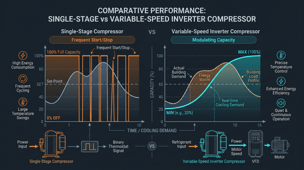
Traditional fixed-speed compressors operate at a single speed, typically 3,450 RPM on 60 Hz power in North America. They run at full capacity until the thermostat is satisfied, then shut off entirely. This on/off cycling creates temperature swings of 2 to 4 degrees Fahrenheit in the conditioned space, wastes energy during startup surges (inrush current can reach six to eight times running current), and places mechanical stress on bearings, valves, and windings with every start.
Variable Speed Compressors: The Core Concept
A variable speed compressor adjusts its rotational speed, and therefore its refrigerant pumping capacity, to closely match the actual thermal load of the building at any given moment. Instead of delivering 100% capacity or 0%, it might operate at 30% on a mild spring afternoon and ramp to 95% during a peak summer heatwave.
This modulation produces several immediate benefits: energy consumption drops because the compressor avoids repeated high-current startups and runs at efficient part-load conditions; indoor temperatures hold within approximately 0.5 degrees Fahrenheit of setpoint; dehumidification improves because slower airflow across the evaporator coil extracts more moisture per unit of air; and noise levels fall significantly at reduced speeds. The tradeoffs include higher equipment cost, greater electronic complexity, and the need for technicians trained in inverter diagnostics.
The key enabler is speed control. By varying compressor RPM, the system controls refrigerant mass flow rate through the circuit, directly adjusting the rate of heat absorption or rejection. This is where inverter technology enters the picture.
Inverter Technology: The Engine of Variable Speed
An inverter is an electronic power conversion device that takes incoming AC (alternating current) line power, converts it to DC (direct current), and then reconstructs it as AC output at a variable frequency and voltage. By changing the output frequency, the inverter controls the speed of the compressor motor. A 30 Hz output signal, for example, runs the motor at roughly half the speed of a 60 Hz signal.
The Inverter Process: Step by Step
The power conversion inside an HVAC inverter follows three distinct stages.
Rectification: Incoming 208 to 230V AC power first passes through a rectifier circuit, typically a full-bridge arrangement of power diodes, which converts alternating current into pulsating direct current. Many modern inverter boards incorporate Power Factor Correction (PFC) circuitry at this stage. PFC reshapes the input current waveform to closely follow the voltage waveform, improving the power factor to 0.95 or higher and reducing harmonic current drawn from the utility grid.
Filtering: The pulsating DC output from the rectifier passes through a bank of DC bus capacitors, typically aluminum electrolytic capacitors rated at 400 to 450V DC. These capacitors smooth the voltage ripple into a stable DC bus, usually in the range of 300 to 400V DC for residential systems. Capacitor selection is critical for reliability; undersized or degraded capacitors cause voltage ripple that stresses downstream components and reduces motor efficiency. DC bus capacitors are among the most failure-prone components in inverter assemblies and are a common service item.
Inversion: The stable DC bus voltage feeds into the inverter output stage, where insulated-gate bipolar transistors (IGBTs) rapidly switch the DC voltage to synthesize an AC output. A typical residential HVAC inverter uses six IGBTs arranged in a three-phase bridge configuration, with voltage ratings of 600V to 1200V and current ratings from 15A to 50A depending on system capacity. IGBTs are the dominant power semiconductor in current HVAC inverters, though emerging silicon carbide (SiC) and gallium nitride (GaN) devices are beginning to appear in premium equipment, offering lower switching losses, higher temperature tolerance, and improved efficiency at high switching frequencies.
Pulse-Width Modulation: The Control Technique
Pulse-Width Modulation (PWM) is the method by which the inverter’s IGBTs create a usable AC signal from DC voltage. Rather than producing a smooth sine wave directly, the IGBTs switch on and off thousands of times per second, typically at carrier frequencies between 4 kHz and 16 kHz. Each switching pulse has a controlled width, or duty cycle, representing the proportion of time the voltage is on versus off within each switching period.
By varying the duty cycle of these pulses over time following a sinusoidal pattern, the average voltage delivered to the motor traces a sine wave shape. The motor’s own winding inductance acts as a natural low-pass filter, smoothing the rapid voltage pulses into a near-sinusoidal current waveform. This technique is called sinusoidal PWM (SPWM). A more advanced approach, space vector PWM (SVPWM), optimizes switching sequences to reduce harmonic content and improve DC bus voltage utilization by approximately 15% compared to standard SPWM.
The output frequency of the reconstructed AC signal determines motor speed. Residential HVAC inverters typically produce output frequencies ranging from 15 to 20 Hz at minimum speed up to 120 Hz or higher at maximum speed, giving the compressor a speed range of roughly 900 RPM to over 7,000 RPM.
Control Strategies and Sensor Inputs
The inverter’s microprocessor continuously adjusts compressor speed based on feedback from multiple sensors throughout the system. Common inputs include:
- Suction and discharge pressure transducers
- Suction and discharge temperature thermistors
- Outdoor ambient temperature sensor
- Indoor return air temperature and humidity sensors
- Compressor shell temperature sensor
- DC bus voltage and output current measurements
Sophisticated PID (Proportional-Integral-Derivative) control algorithms process these inputs to determine the optimal compressor frequency at any moment. Advanced systems use field-oriented control (FOC), also known as vector control, which independently manages the torque-producing and flux-producing components of motor current for maximum efficiency across the entire speed range. Many modern inverter compressors employ sensorless control techniques that estimate rotor position from back-EMF measurements, eliminating the need for physical position sensors on the motor.
Inverter Topologies
The vast majority of HVAC inverters use a Voltage Source Inverter (VSI) topology, where the DC bus maintains a constant voltage and the output is modulated using PWM. VSI designs are simple, efficient, and well-suited to the power ranges of residential and light commercial equipment. Current Source Inverters (CSI) maintain a constant DC bus current instead of voltage and find occasional use in larger commercial applications, particularly some centrifugal chiller drives, where their inherent short-circuit protection offers advantages.
Technical Specifications and Performance Parameters
Motor Types
Variable speed compressors pair with specific motor technologies to maximize performance. Permanent Magnet Synchronous Motors (PMSM) are the preferred choice in high-efficiency systems. They use rare-earth magnets (typically neodymium) on the rotor, delivering efficiency ratings above 95% across a wide speed range with excellent torque density. Brushless DC motors (BLDC) are closely related to PMSMs and are common in ductless mini-split systems and smaller capacity equipment. Induction motors can also operate with inverter control but suffer efficiency penalties at low speeds due to rotor slip losses, making them less common in premium variable speed residential equipment.
Efficiency Ratings and Standards
Variable speed inverter systems achieve their high efficiency ratings primarily through part-load performance. A variable speed heat pump might carry a SEER2 rating of 20 to 24 or higher, compared to 14 to 16 for a single-stage system. HSPF2 ratings for heating follow a similar pattern. The inverter’s own conversion efficiency, typically 95% to 98% for modern designs, contributes to overall system performance. Equipment is certified through AHRI (Air-Conditioning, Heating, and Refrigeration Institute) testing procedures, and manufacturers must comply with DOE minimum efficiency standards.
Harmonic Distortion
Inverters draw non-sinusoidal current from the grid, introducing harmonic distortion that can affect power quality. The IEEE 519 standard sets limits on harmonic current injection at the point of common coupling. Modern HVAC inverters address this through input line reactors, DC bus chokes, and active PFC circuits that keep total harmonic distortion (THD) within acceptable limits, typically below 5% to 10% of fundamental current for equipment with PFC.
Advantages and Disadvantages
Advantages
- Energy efficiency: Variable speed systems consume 30% to 50% less energy than comparable single-stage systems in typical residential applications, with the greatest savings occurring in climates with long, moderate shoulder seasons.
- Temperature consistency: Continuous modulation maintains indoor temperatures within 0.5 degrees Fahrenheit of setpoint, eliminating the 2 to 4 degree swings common with on/off cycling.
- Dehumidification: At lower speeds, the evaporator coil temperature stays consistently below the dew point for longer periods, removing 10% to 20% more moisture compared to single-stage operation at equivalent sensible loads.
- Noise reduction: A compressor running at 30% speed produces significantly less noise than one running at 100%. Many variable speed outdoor units operate below 55 dBA at minimum speed.
- Equipment longevity: Fewer start/stop cycles reduce mechanical wear on compressor bearings, scroll elements, and electrical contactors. Soft-start capability eliminates inrush current stress on windings and power supply components.
Disadvantages
- Higher initial cost: Variable speed systems typically cost 30% to 60% more than single-stage equivalents, including the outdoor unit, matched indoor coil, and compatible thermostat or control board.
- Repair complexity: Diagnosing inverter board failures requires oscilloscopes, multimeters capable of measuring DC bus voltage, and manufacturer-specific diagnostic software. Replacement inverter boards can cost $500 to $1,500 for parts alone.
- Power quality sensitivity: Voltage sags below 187V, surges above 253V, and sustained brownout conditions can damage rectifier components and DC bus capacitors. Surge protection is strongly recommended for all inverter-driven systems.
- Electromagnetic interference: The high-frequency switching of IGBTs generates EMI (electromagnetic interference) that can affect nearby electronics. Proper shielding, ferrite cores on communication wiring, and input/output filtering are required to meet FCC Part 15 emission limits.
Common Misconceptions
“Inverter technology is only for cooling.” Inverter-driven compressors operate in both cooling and heating modes. In heat pump applications, variable speed is particularly valuable because heating loads vary widely with outdoor temperature, and the compressor must ramp up capacity as outdoor temperatures fall.
“Variable speed always guarantees higher efficiency.” An improperly sized system, incorrect refrigerant charge, restricted airflow, or poorly designed ductwork can negate the benefits of variable speed operation. Proper installation and commissioning are essential. An oversized variable speed system may short-cycle at minimum speed, reducing dehumidification and efficiency.
“All variable speed systems perform the same.” Significant differences exist among manufacturers in inverter topology, control algorithm sophistication, motor type, and minimum-to-maximum speed range. A system with a 10:1 turndown ratio offers more precise modulation than one with a 3:1 ratio.
“Inverters are unreliable.” Early inverter boards earned a mixed reputation, but modern designs using conformal-coated circuit boards, improved thermal management, and robust DC bus capacitors have substantially improved field reliability. Choosing established manufacturers and ensuring clean power supply conditions further reduces failure risk.
Practical Applications
Residential systems: Inverter-driven compressors are standard in ductless mini-split systems and increasingly common in ducted split-system air conditioners and heat pumps. Premium residential units from major manufacturers now offer SEER2 ratings above 22 with variable speed compressors as the enabling technology.
Commercial systems: Variable Refrigerant Flow (VRF) systems rely entirely on inverter-driven compressors to simultaneously serve dozens of indoor zones from a single outdoor unit. Commercial chillers with variable speed centrifugal or screw compressors achieve integrated part-load values (IPLV) 30% to 40% better than constant speed equivalents.
Refrigeration: Commercial refrigeration cases, walk-in coolers, and supermarket rack systems increasingly use inverter compressors to maintain tighter temperature control and reduce energy consumption during low-demand periods.
Future trends: Machine learning algorithms are being integrated into inverter control systems to predict load patterns based on weather data, occupancy schedules, and historical usage, further optimizing compressor speed selection. The adoption of SiC and GaN power semiconductors will push inverter switching frequencies higher while reducing conversion losses, enabling smaller, lighter, and more efficient inverter assemblies.
Related Topics
Variable speed compressor technology intersects with several important HVAC topics. The transition to low-GWP refrigerants such as R-32 and R-454B affects inverter system design because these refrigerants have different pressure-enthalpy characteristics and, in some cases, mild flammability (A2L classification) requiring additional safety controls. Smart home integration allows variable speed systems to communicate with platforms like Google Home, Amazon Alexa, and Apple HomeKit for remote monitoring, scheduling, and demand response participation. Integration with Building Automation Systems (BAS) through BACnet or Modbus protocols enables centralized optimization of variable speed equipment across large commercial facilities. Technicians working on inverter systems should be familiar with DC bus voltage measurement, IGBT testing procedures, and manufacturer-specific fault code interpretation.
Key Takeaways
- Variable speed compressors use inverter technology to adjust motor speed and match real-time heating or cooling demand, replacing the inefficient on/off cycling of traditional fixed-speed systems.
- The inverter converts AC line power to DC, then reconstructs variable-frequency AC using IGBTs and PWM techniques to control compressor speed precisely.
- Energy savings of 30% to 50% are achievable, along with tighter temperature control, improved dehumidification, and lower noise levels.
- Higher initial cost, increased repair complexity, and sensitivity to power quality are real tradeoffs that should factor into system selection and installation planning.
- Proper sizing, installation, and commissioning are essential to realize the full performance potential of any variable speed system.
- Advancing semiconductor materials like SiC and GaN, combined with AI-driven control algorithms, will continue to improve inverter efficiency and intelligence in coming years.