Mini-Split Systems: Installation, Sizing, and Troubleshooting
Mini-split systems have become one of the fastest-growing segments in the HVAC market, with global demand increasing by more than 10% annually over the past five years. Their appeal is straightforward: they deliver efficient heating and cooling without requiring ductwork, they allow precise zone control, and they fit applications ranging from single-room additions to whole-house climate management. A mini-split system consists of at least one outdoor unit containing the compressor and condenser and one or more indoor units that house the evaporator and blower. Refrigerant lines, electrical wiring, and a condensate drain connect the two through a small penetration in the wall, typically just three inches in diameter. This article covers the essential knowledge every homeowner and HVAC technician needs: how these systems work, how to install them correctly, how to size them accurately, and how to diagnose and fix the most common problems.
System Components and Operation
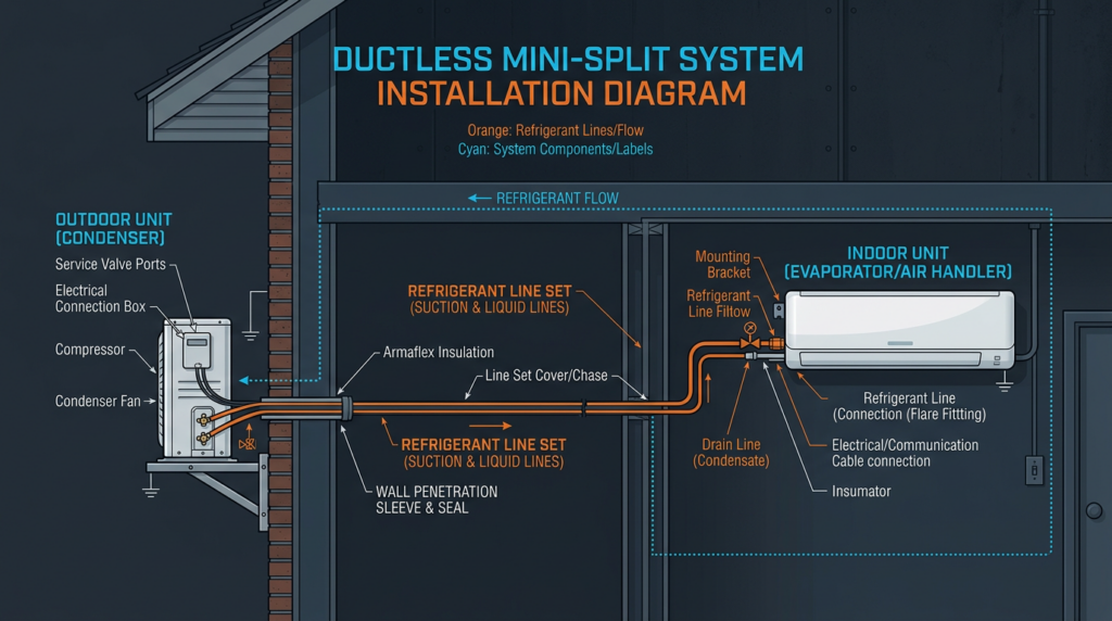
Outdoor Unit (Condenser/Compressor)
The outdoor unit is the powerhouse of the system. It contains the compressor, which pressurizes refrigerant and circulates it through the system, along with a condenser coil, a fan, and an expansion device. Modern mini-splits almost exclusively use inverter-driven compressors, either scroll or rotary type, which vary their speed to match the heating or cooling demand in real time. This variable-speed operation is what gives mini-splits their high efficiency ratings. In cooling mode, the outdoor unit rejects heat from the refrigerant to the outside air. In heating mode, it reverses the cycle and absorbs heat from the outdoor air, functioning as a heat pump.
Indoor Unit (Air Handler/Evaporator)
The indoor unit absorbs heat from the room during cooling and releases heat into the room during heating. It contains an evaporator coil, a blower fan (axial or centrifugal depending on the unit type), washable air filters, and a condensate drain connection. Indoor units come in several configurations:
- Wall-mounted: The most common type, installed high on the wall for wide air distribution
- Ceiling cassette: Recessed into the ceiling for a low-profile appearance, distributing air in two or four directions
- Floor-mounted: Positioned near floor level, ideal for rooms with limited wall space or large windows
- Slim duct (ducted): Concealed above the ceiling with short duct runs, offering a completely hidden installation
Refrigerant Lines and Refrigerant Types
Refrigerant lines consist of a liquid line (smaller diameter) and a suction line (larger diameter, insulated) that transfer refrigerant between the indoor and outdoor units. The refrigerant type matters significantly for both performance and environmental compliance. R-410A has been the industry standard for years but is being phased down under the AIM Act and EPA regulations due to its high global warming potential (GWP of 2,088). Newer systems increasingly use R-32 (GWP of 675), R-454B (GWP of 466), or in some cases R-290 (propane, GWP of 3). Technicians must follow EPA Section 608 regulations for refrigerant handling and stay current with local codes governing the use, recovery, and disposal of all refrigerant types. As of 2025, new equipment manufacturing is shifting heavily toward R-32 and R-454B, and technicians should expect to encounter these refrigerants regularly.
Control System
Each mini-split system includes a control board in both the indoor and outdoor units, a wireless remote control, and often an optional wired thermostat. The control system manages temperature setpoints, fan speed, operating mode (cooling, heating, auto, dry/dehumidify, fan only), swing louver positions, timers, and sleep modes. Most current-generation units offer Wi-Fi connectivity for integration with smart home platforms like Google Home, Amazon Alexa, and Apple HomeKit, allowing remote monitoring and scheduling through smartphone apps.
Mini-Split Installation Best Practices
Site Selection
Proper placement of both units is critical to performance and longevity. For the outdoor unit, select a location with at least 24 inches of clearance on all sides for airflow, protected from direct afternoon sun when possible, and elevated above expected snow lines in cold climates. Keep the unit away from bedroom windows and property lines to minimize noise complaints; most outdoor units produce 48 to 58 dB at rated conditions. For the indoor unit, mount it on an exterior wall to minimize refrigerant line length, position it where airflow can circulate freely across the room, and avoid placing it directly above televisions, beds, or heat-generating appliances. Always verify local building codes and permit requirements before beginning installation.
Mounting
The outdoor unit requires a stable, level surface. Use a concrete pad (at least 3 inches thick) or a wall-mounting bracket rated for the unit’s weight, typically 80 to 130 pounds. Install rubber vibration-dampening pads between the unit and the mounting surface to reduce noise transmission. The indoor unit must be fastened securely to wall studs or ceiling joists using the manufacturer’s mounting plate. Wall-mounted units should be installed approximately 7 feet above the floor and slightly tilted toward the drain side (about 1/4 inch) to promote condensate flow.
Refrigerant Line Connections
Refrigerant line connections are where many installation failures originate. Proper technique is essential:
- Cut copper tubing squarely using a tube cutter, then ream the inside edge to remove burrs
- Create flares using a quality eccentric flaring tool designed for the tubing diameter
- Apply a thin layer of refrigerant oil (ester oil for R-410A, POE oil for R-32/R-454B) to the flare surface
- Hand-tighten flare nuts first, then use a torque wrench to tighten to the manufacturer’s specified torque value (typically 33 to 51 ft-lbs for 3/8-inch fittings, varying by brand)
- Route lines to avoid sharp bends (minimum bend radius of 4 inches for 3/8-inch tubing) and protect them with line set covers or insulation rated for outdoor UV exposure
Electrical Connections
Disconnect all power before performing any electrical work. Mini-splits require a dedicated circuit from the electrical panel. Smaller units (9,000 to 12,000 BTU/h) typically run on 115V/15A circuits, while larger units (18,000 to 36,000 BTU/h) require 208-230V/20A to 30A circuits. Install a disconnect switch within sight of the outdoor unit as required by the National Electrical Code (NEC). Recent NEC updates (2023 cycle) include revised requirements for overcurrent protection and disconnect ratings specific to heat pump equipment. Always reference the unit’s wiring diagram, use appropriately rated wire gauge (typically 14 AWG for 15A circuits, 10 AWG for 30A circuits), and ensure proper grounding.
Vacuuming, Pressure Testing, and Charging
Before opening the service valves, the refrigerant lines and indoor unit must be evacuated to remove moisture and non-condensable gases. The correct procedure is:
- Nitrogen purge: Flow dry nitrogen through the line set to displace contaminants
- Pressure test: Pressurize the system with nitrogen to 400 to 500 psi (or per manufacturer specs) and hold for at least 30 minutes to verify zero pressure drop, confirming no leaks exist
- Evacuation: Connect a vacuum pump and pull the system down to 500 microns or below, as measured by a micron gauge (not the vacuum pump’s gauge). Allow the system to stand for 10 minutes and verify the vacuum holds below 800 microns
- Charging: Most pre-charged outdoor units include enough refrigerant for up to 25 feet of line set. For longer runs, add refrigerant by weight according to the manufacturer’s specification (typically 0.6 to 0.8 ounces per additional foot of liquid line). Use a digital refrigerant scale for accuracy
Condensate Drain and System Commissioning
Route the condensate drain line with a minimum slope of 1/4 inch per foot to ensure gravity drainage. If gravity drainage is not possible, install a condensate pump rated for the unit’s output. After completing all connections, perform a full system commissioning: verify heating and cooling operation, check supply and return air temperature differentials (typically 18 to 22 degrees Fahrenheit in cooling mode), inspect all electrical connections with a multimeter, and confirm there are no refrigerant leaks using an electronic leak detector. Document the installation and educate the homeowner on filter cleaning, remote control operation, and seasonal maintenance.
Sizing Mini-Split Systems
Why Proper Sizing Matters
An undersized system will run continuously without reaching the setpoint, leading to excessive energy consumption, accelerated wear, and occupant discomfort. An oversized system will short cycle, turning on and off frequently, which degrades humidity control (particularly problematic in cooling mode), wastes energy during startup surges, and reduces equipment lifespan. Correct sizing is not optional; it is the foundation of a successful installation.
Manual J Load Calculation
The industry-standard method for determining heating and cooling loads is the ACCA Manual J calculation. This calculation accounts for all variables that affect the thermal load on a space:
- Climate data: Local design temperatures for heating and cooling, humidity levels, and solar radiation intensity
- Building envelope: Insulation R-values for walls, roof, and floor; window U-factors and solar heat gain coefficients; air leakage rates measured in ACH (air changes per hour)
- Occupancy: Number of people (each person contributes roughly 250 to 400 BTU/h of sensible and latent heat)
- Internal loads: Heat from lighting, cooking appliances, electronics, and other equipment
- Orientation and shading: South and west-facing windows increase cooling loads significantly
The result is expressed in BTU/h (British thermal units per hour). One ton of cooling capacity equals 12,000 BTU/h. A typical well-insulated bedroom might require 6,000 to 9,000 BTU/h, while a large open-plan living area could need 18,000 to 24,000 BTU/h.
Multi-Zone Systems and Manufacturer Ratings
For multi-zone systems, calculate the load for each individual zone and then select an outdoor unit with capacity to serve the combined peak load. Be aware that the total connected indoor unit capacity often exceeds the outdoor unit’s rated capacity (sometimes by up to 130%), a practice called overconnection that works because zones rarely all peak simultaneously. When reviewing manufacturer specifications, pay close attention to SEER2 (Seasonal Energy Efficiency Ratio 2) and HSPF2 (Heating Seasonal Performance Factor 2) ratings, which reflect the updated M1 testing procedures effective since January 2023. Also check the unit’s rated heating capacity at 47 degrees Fahrenheit and at 17 degrees Fahrenheit, and verify the minimum operating temperature for heating mode, which ranges from 5 degrees Fahrenheit to minus 22 degrees Fahrenheit depending on the model. As a general guideline, avoid oversizing by more than 10% beyond the calculated load.
Common Problems and Troubleshooting
General Troubleshooting Approach
Before calling for service, perform these basic checks: inspect air filters for dirt buildup, verify the unit has power and the circuit breaker has not tripped, replace the remote control batteries, and note any error codes displayed on the indoor unit’s LED panel. Error codes vary by manufacturer but follow common patterns. For example, communication errors between indoor and outdoor units (often displayed as E1 or U1) typically indicate wiring faults or a failed control board. Consult the manufacturer’s service manual for code-specific guidance.
Common Problems and Solutions
- Unit not turning on: Check the power supply, breaker, disconnect switch, and control board fuse. Test voltage at the outdoor unit terminals with a multimeter. Verify the indoor unit is receiving the 12 to 15 VDC signal from the control board.
- Insufficient cooling or heating: Clean or replace air filters (every 2 to 4 weeks during heavy use). Clean evaporator and condenser coils with a no-rinse coil cleaner. Check for refrigerant leaks at flare connections (requires a licensed technician for repair and recharge). Verify the unit is properly sized for the space.
- Water leaking from indoor unit: The most common cause is a clogged condensate drain line. Flush the drain with a mixture of warm water and mild bleach. Check for a frozen evaporator coil, which indicates restricted airflow or low refrigerant charge. Replace a failed condensate pump if installed.
- Unusual noises: Rattling often indicates loose mounting hardware or debris in the fan assembly. A hissing sound at the indoor unit may indicate normal refrigerant flow through the expansion device or, if persistent, a refrigerant leak. Compressor noise that exceeds normal operating levels (typically 55 to 62 dB outdoors) warrants professional diagnosis.
- Ice buildup on outdoor unit in heating mode: Check that nothing is blocking airflow around the unit. Verify the defrost cycle is functioning; the system should initiate a defrost cycle every 30 to 90 minutes during cold, humid conditions. Persistent icing suggests low refrigerant charge or a faulty defrost sensor, both of which require a licensed technician.
- Short cycling: Frequently caused by an oversized unit, restricted airflow from dirty filters, or a malfunctioning thermistor. Check and clean filters first, then verify proper sizing against the space’s load calculation.
Essential Troubleshooting Tools
- Multimeter: Measures voltage, amperage, resistance, and capacitance for electrical diagnostics
- Infrared thermometer: Measures surface temperatures on coils and refrigerant lines to assess system performance
- Refrigerant gauges and leak detector: Required for pressure measurements and leak detection (EPA 608 certification required for refrigerant work)
- Anemometer: Measures airflow velocity to verify proper CFM output from the indoor unit
Any work involving refrigerant recovery, repair, or recharging must be performed by a technician holding an EPA Section 608 certification. Venting refrigerant is a federal violation with significant penalties.
Common Misconceptions
Several persistent myths surround mini-split systems. The belief that they only work for small spaces is outdated; multi-zone systems with up to eight indoor units connected to a single outdoor unit can condition an entire home exceeding 3,000 square feet. The assumption that mini-splits cannot handle extreme cold is also increasingly inaccurate, as cold-climate models from manufacturers like Mitsubishi (Hyper-Heating), Fujitsu, and LG maintain rated heating capacity down to minus 13 degrees Fahrenheit or lower. Mini-splits are not inherently expensive to operate. Units with SEER2 ratings of 20 or higher and HSPF2 ratings above 10 consistently outperform conventional systems in energy cost comparisons. Finally, while professional installation is strongly recommended, the ductless design means installation is significantly less invasive than traditional ducted systems, often completed in a single day.
Practical Applications
Mini-splits excel in a wide range of settings. In residential applications, they provide efficient supplemental conditioning for room additions, converted garages, attics, and sunrooms where extending existing ductwork is impractical or costly. In commercial settings, they serve individual offices, retail storefronts, restaurants, and server rooms where precise temperature control and independent zoning are required. Specialized applications include greenhouses, wine cellars, and workshops where humidity and temperature must be tightly regulated.
Key Takeaways
Mini-split systems deliver reliable, efficient heating and cooling when installed and sized correctly. Always perform a Manual J load calculation before selecting equipment, and resist the temptation to oversize. Follow manufacturer installation procedures precisely, especially for flare connections, evacuation, and electrical work. Clean filters regularly, keep coils free of debris, and flush condensate drains seasonally. Stay current on refrigerant regulations as the industry transitions from R-410A to lower-GWP alternatives like R-32 and R-454B. For any work involving refrigerant handling, electrical panel modifications, or complex diagnostics, consult a qualified HVAC professional with the appropriate certifications and local licensing.