Blower Motor Troubleshooting: ECM vs PSC Motors
A homeowner calls in frustrated: the furnace keeps cycling on and off, airflow from the vents feels weak, and the energy bills have spiked for no apparent reason. For HVAC technicians, these complaints often trace back to a single component that sits at the heart of every forced-air system: the blower motor. This motor drives the fan that circulates conditioned air through ductwork for heating, cooling, and ventilation. When it fails or underperforms, the entire system suffers. The two primary types of blower motors found in residential and light commercial HVAC systems are PSC (Permanent Split Capacitor) motors and ECM (Electronically Commutated Motors). Each uses fundamentally different technology, fails in different ways, and demands different diagnostic approaches. This guide breaks down the technical differences, common failure modes, step-by-step troubleshooting procedures, and repair-versus-replacement considerations for both motor types, giving technicians the knowledge to resolve airflow problems efficiently and accurately.
Understanding ECM and PSC Motors: Technical Differences
Before picking up a multimeter, technicians need a solid understanding of how each motor type operates. Misidentifying the motor or applying the wrong diagnostic procedure wastes time and can damage components.
PSC Motors: The Industry Workhorse
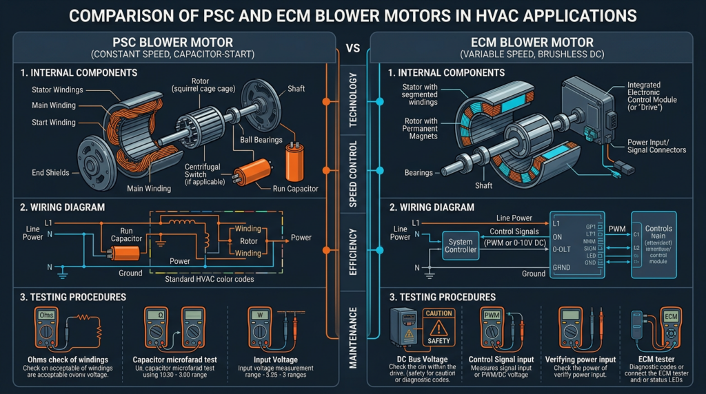
The PSC motor has been the standard blower motor in HVAC systems for decades. It operates on a simple principle: a run capacitor creates a phase shift between the start winding and the run winding currents, generating a rotating magnetic field that drives the rotor. The capacitor remains in the circuit during operation, which is what distinguishes PSC motors from other single-phase induction motors.
Key technical specifications include:
- Voltage: Typically 115V or 230V AC single-phase
- Horsepower: Common ratings of 1/5 HP, 1/4 HP, 1/3 HP, and 1/2 HP
- Speed control: 3 to 5 discrete speeds selected by tapping into different motor windings
- Typical amperage: Ranges from approximately 2A to 8A depending on HP rating and speed tap
- Efficiency: Approximately 45% to 65% at rated load
The primary advantages of PSC motors are their simplicity, low purchase cost (often $75 to $200), and straightforward repair process. Their main drawbacks include lower energy efficiency, a fixed torque-to-speed curve, and limited airflow precision since they can only operate at preset speed taps rather than continuously variable speeds.
ECM Motors: The Smart Option
ECM motors represent a significant technological step forward. These are brushless DC motors with a permanent magnet rotor and an integrated electronic control module that converts incoming AC power to DC and uses an inverter circuit to electronically commutate the motor windings. This electronic commutation replaces the mechanical brushes found in traditional DC motors, resulting in higher efficiency and longer service life.
Key technical specifications include:
- Voltage: Typically 115V or 230V AC input (converted internally to DC)
- Horsepower: Similar ranges to PSC motors, from 1/5 HP to 1 HP
- Speed control: Continuously variable, typically controlled via PWM signals, 0-10V signals, or serial communication from the system control board
- Efficiency: Approximately 70% to 85%, with some models exceeding 80% across a wide operating range
- Advanced features: Soft start and stop, constant airflow programming, onboard diagnostics, and fault code reporting
Technicians should understand the three main ECM operating modes:
- Constant torque ECM motors: Maintain a set torque output and adjust speed based on static pressure changes. Common in entry-level variable-speed systems.
- Constant CFM (airflow) ECM motors: Automatically adjust speed to deliver a programmed airflow volume regardless of duct resistance. These are the most common in mid-range to high-end residential systems.
- Variable CFM ECM motors: Allow the system controller or building automation system to command specific airflow rates dynamically based on real-time demand.
ECM motors have also evolved through multiple generations. Earlier Gen 1 and Gen 2 models used simple speed tap wiring similar to PSC motors but with electronic control. Gen 3 and newer models communicate via serial data links with the furnace or air handler control board, offering greater precision but also greater diagnostic complexity. Physically, ECM motors are identifiable by the control module (a rectangular or cylindrical housing containing circuit boards) mounted directly to the motor body. PSC motors lack this module entirely.
Common Blower Motor Problems: Symptoms and Causes
Problems Affecting Both Motor Types
Several failure modes are universal to blower motors regardless of type:
- Motor won’t start or produces a humming noise: Causes include thermal overload tripping, locked rotor from seized bearings, faulty wiring connections, low supply voltage (below 10% of nameplate rating), or debris jamming the blower wheel. Symptoms range from complete silence to a distinct hum with no shaft rotation, often accompanied by a tripped breaker.
- Overheating and intermittent shutdown: Dirty air filters, blocked return ducts, failing bearings creating excessive friction, incorrect voltage supply, or high ambient temperatures in the equipment closet can all cause the motor’s internal thermal overload to trip. The motor shuts down, cools off, and restarts in a frustrating cycle. A burning smell often accompanies this condition.
- Excessive noise and vibration: Worn bearings produce squealing or grinding sounds. Loose mounting brackets cause rattling. An unbalanced or damaged blower wheel creates a rhythmic vibration that worsens at higher speeds.
- Repeated breaker trips or blown fuses: Short circuits within the motor windings, a locked rotor drawing excessive current, or ground faults between windings and the motor housing will cause overcurrent protection to activate.
Problems Specific to PSC Motors
- Capacitor failure: This is the single most common PSC motor issue. Capacitors degrade from age, heat exposure, and voltage spikes. A failed capacitor may appear swollen, cracked, or leaking oil. Symptoms include failure to start (sometimes with a humming sound), sluggish startup, or the motor running at reduced speed. A capacitor that has lost more than 10% of its rated microfarad value should be replaced.
- Speed control issues: A faulty speed selector switch on the control board or damaged windings at specific speed taps can cause the motor to operate on only one speed or fail entirely on certain settings.
Problems Specific to ECM Motors
- Control module failure: The integrated electronics are vulnerable to voltage spikes, sustained overheating, and component-level failures (blown MOSFETs, failed capacitors on the circuit board). Symptoms include complete motor failure, erratic speed changes, or error codes displayed on the furnace control board.
- Communication errors: Wiring problems between the system control board and the ECM module, a faulty furnace control board, or incompatible replacement components can prevent the motor from receiving speed commands. The motor may default to a single speed or not run at all.
- Incorrect programming or configuration: Improperly set DIP switches, incorrect airflow parameters programmed during installation, or software glitches following a power surge can result in the motor running at the wrong speed, delivering inadequate airflow, or cycling abnormally.
Troubleshooting ECM and PSC Motors: A Step-by-Step Guide
Safety First
Always disconnect power at the breaker and verify zero voltage with a multimeter before touching any wiring or components. Capacitors in both PSC and ECM circuits can store lethal charges. Wear appropriate personal protective equipment including insulated gloves and safety glasses. Lock out and tag out the disconnect when working on commercial equipment.
Basic Inspection for All Motor Types
- Visual inspection: Look for burnt, melted, or discolored wiring. Check for swollen or leaking capacitors. Inspect the motor housing and control module for signs of heat damage, corrosion, or physical impact.
- Airflow verification: Confirm the air filter is clean and properly seated. Inspect accessible ductwork for obstructions, collapsed flex duct, or closed dampers. A restricted system can cause motor failure even when the motor itself is healthy.
- Voltage check: With power restored, measure supply voltage at the motor terminals under load using a multimeter. Voltage should be within plus or minus 10% of the motor’s nameplate rating. Low voltage is a frequent and overlooked cause of motor problems.
PSC Motor Troubleshooting
- Capacitor testing: Disconnect power and safely discharge the capacitor by shorting its terminals through a 20,000-ohm, 5-watt resistor. Remove the capacitor from the circuit and measure its capacitance with a multimeter set to the microfarad scale. Compare the reading to the value printed on the capacitor label. Replace if the measured value is more than 6% below the rated value. A standard run capacitor for residential blower motors typically falls between 5 and 15 microfarads at 370V or 440V.
- Winding resistance test: With power off and the motor disconnected, measure resistance between each speed tap wire and the common wire using an ohmmeter. Readings should typically fall between 1 and 30 ohms depending on the winding. An open reading (OL) indicates a broken winding. A reading near zero suggests a shorted winding. Compare readings to manufacturer specifications when available.
- Ground fault test: Set the multimeter to its highest resistance scale and measure between each motor lead and the motor housing. Any reading below 1 megohm indicates a ground fault, and the motor should be replaced.
- Speed selector switch test: Test the speed selection relay or switch on the control board for proper continuity in each position.
- Bearing check: With the motor accessible, spin the shaft by hand. It should rotate freely and smoothly with no grinding, rough spots, or excessive radial play. Worn bearings require motor replacement in sealed bearing designs or re-oiling in motors with oil ports.
ECM Motor Troubleshooting
- Supply voltage verification: Confirm proper line voltage (115V or 230V AC) at the motor module input terminals. Also verify that 24V AC control power is present if the motor requires a separate low-voltage supply.
- Control signal verification: Using a multimeter, check for the presence of a speed command signal from the furnace control board. For PWM-controlled motors, measure DC voltage at the signal wire (typically 0 to 5V or 0 to 10V corresponding to minimum and maximum speed). For serial communication models, signal verification may require manufacturer-specific diagnostic tools.
- Error code interpretation: Check the furnace or air handler control board for blinking LED fault codes. Cross-reference these codes with the manufacturer’s service manual. Common codes relate to overcurrent, communication loss, overtemperature, and locked rotor conditions. The ECM module itself may also have diagnostic LEDs.
- Resistance checks: Measure motor winding resistance at the module output terminals (with the module disconnected). Three-phase ECM windings should show balanced resistance across all three phases. Significant imbalance or open readings indicate internal motor damage.
- Specialized testing tools: ECM motor testers such as the Rescue Motor Mate or the GE ECM Service Tool can power the motor independently of the system, bypassing the control board entirely. This isolates whether the fault lies in the motor or the system controls. Some manufacturers also offer smartphone apps for Bluetooth-enabled ECM modules that provide real-time diagnostics including RPM, torque output, watt consumption, and fault history.
- Advanced signal analysis: For intermittent communication faults, an oscilloscope can reveal signal integrity issues such as noise, incorrect pulse widths, or timing errors on the communication bus. This level of diagnosis is typically reserved for persistent problems that resist standard troubleshooting.
Always consult the manufacturer’s service manual for model-specific procedures, wiring diagrams, and specifications. Generic procedures provide a starting framework, but ECM motors in particular vary significantly between manufacturers and generations.
Repair vs. Replacement: Making the Right Decision
PSC Motor Decisions
PSC motors offer several cost-effective repair options. Capacitor replacement costs $10 to $30 in parts and takes minutes to complete. Wiring repairs and relay replacements are similarly economical. However, replacement is warranted when windings are damaged, bearings are seized in sealed motor designs, or the motor has been in service for 15 or more years. A new PSC motor typically costs $75 to $250 plus labor, making the repair-versus-replace calculation straightforward when repair costs exceed 50% of replacement cost.
ECM Motor Decisions
ECM motors present a different cost equation. The control module and motor are often sold as a single assembly, with replacement costs ranging from $400 to $1,200 or more. Component-level repair of the control module circuit board is technically possible but requires advanced electronics skills, specialized equipment, and sourcing individual components, making it impractical for most service operations. When the control module fails, full motor replacement is usually the most reliable and cost-effective path. When only wiring or connector issues are involved, repair is obviously preferable. Always check warranty status, as many ECM motors carry 5-year or even 10-year manufacturer warranties.
Key Factors in the Decision
- Compare total repair cost (parts plus labor) against replacement cost
- Consider the motor’s age and remaining useful life
- Verify warranty coverage before purchasing replacement parts
- Evaluate whether upgrading a PSC system to an ECM motor makes sense based on the customer’s usage patterns and energy costs
- Ensure any replacement motor is compatible with the existing control board, wiring harness, and mounting configuration
Common Misconceptions and Best Practices
Misconceptions Worth Correcting
- “All ECM motors are the same.” Constant torque, constant CFM, and variable CFM models behave differently and require different diagnostic approaches. Substituting one type for another without verifying compatibility can create performance problems.
- “A new capacitor fixes any PSC motor.” While capacitor failure is the most common PSC issue, it is far from the only one. Winding failures, bearing seizures, and ground faults all require different solutions.
- “ECM motors always save energy.” ECM motors are generally more efficient, but a constant torque ECM motor fighting high static pressure in a poorly designed duct system may consume more energy than expected. System design matters as much as motor technology.
- “Any technician can work on an ECM motor.” ECM diagnostics require knowledge of electronic control circuits, manufacturer-specific fault codes, and often specialized testing equipment. Inadequate training leads to misdiagnosis and unnecessary part replacements.
Best Practices for Every Service Call
- Document every troubleshooting step, measurement, and finding for future reference and customer records
- Use OEM or verified-compatible replacement parts to avoid warranty and performance issues
- Dispose of old capacitors properly according to local environmental regulations
- Measure and verify system airflow after any motor replacement to ensure proper CFM delivery
- Stay current on ECM technology through manufacturer training, NATE certification programs, and HVAC Excellence courses
- Follow the manufacturer’s installation and service instructions without exception
Related Topics and Further Learning
Blower motor troubleshooting connects to several broader HVAC disciplines. Variable Frequency Drives (VFDs) offer another approach to motor speed control and are increasingly common in commercial applications. Building Automation Systems (BAS) integrate ECM motor controls into facility-wide monitoring and optimization platforms. After any motor replacement, airflow measurement and balancing should be performed to confirm the system delivers design CFM values to each zone. Technicians looking to formalize their expertise should pursue certifications through NATE or HVAC Excellence, both of which cover motor diagnostics in their competency exams.
Key Takeaways
PSC and ECM blower motors serve the same fundamental purpose but differ dramatically in technology, failure modes, and diagnostic requirements. PSC motors are simpler and cheaper to repair, with capacitor failure being the most frequent issue. ECM motors deliver superior efficiency and airflow control but demand specialized knowledge, manufacturer documentation, and often dedicated testing tools for accurate diagnosis. Successful troubleshooting always starts with safety, proceeds through systematic inspection and measurement, and ends with a clear-eyed repair-versus-replacement decision grounded in cost, motor condition, and system compatibility. Whether you are servicing a 20-year-old PSC system or a latest-generation ECM installation, methodical diagnosis and continuous learning remain the most reliable tools in any technician’s kit.