Air Balancing: Measuring and Adjusting HVAC Airflow
The U.S. Department of Energy estimates that the average duct system loses 25 to 40 percent of the energy produced by a central furnace or air conditioner, with poorly balanced airflow accounting for a significant share of that waste. Air balancing is the systematic process of measuring, adjusting, and verifying airflow within an HVAC system to ensure each room or zone receives the precise volume of conditioned air specified in the original design. When done correctly, air balancing eliminates hot and cold spots, reduces energy consumption by 15 to 30 percent, extends equipment life, and improves indoor air quality. This article covers the fundamental principles of HVAC airflow, the tools and techniques professionals use to balance systems, a step-by-step procedural guide, common challenges, and the latest developments shaping the field.
Fundamental Principles of HVAC Airflow
Key System Components
Understanding air balancing requires familiarity with the components that move, distribute, and return conditioned air throughout a building:
- Air Handling Unit (AHU) or Furnace: The central device that conditions and propels air through the system. It houses the blower motor, heating or cooling coils, and filtration.
- Ductwork: The network of rigid sheet metal, fiberglass duct board, or flexible ducts that carries supply and return air. Duct type, diameter, length, and the number of turns all influence airflow resistance.
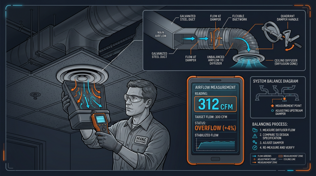
- Registers, Grilles, and Diffusers (RGDs): Supply registers deliver conditioned air into rooms, return grilles pull air back to the AHU, and diffusers spread supply air across a wider area to reduce drafts.
- Dampers: Adjustable plates inside ductwork that throttle or redirect airflow. Manual balancing dampers are set during commissioning, while motorized dampers respond to automated controls in zoned or Variable Air Volume (VAV) systems.
Core Airflow Concepts
- CFM (Cubic Feet per Minute): The standard volumetric measure of airflow. A typical residential system delivers 350 to 450 CFM per ton of cooling capacity. Each room has a design CFM based on its heat load calculation.
- Static Pressure: The resistance air encounters as it moves through ductwork, measured in inches of water column (in. w.c.). Most residential systems are designed for 0.5 in. w.c. or less of total external static pressure. Excessive static pressure signals restrictions such as dirty filters, undersized ducts, or closed dampers.
- Velocity Pressure: The kinetic energy component of moving air, also measured in inches of water column. It reflects how fast air travels through a duct.
- Total Pressure: The sum of static pressure and velocity pressure at any given point. Total pressure always decreases in the direction of airflow due to friction and turbulence losses.
- Air Changes per Hour (ACH): The number of times the total air volume of a room is replaced in one hour. ASHRAE Standard 62.1 and 62.2 specify minimum ventilation rates for commercial and residential buildings, respectively, and proper air balancing ensures those rates are met.
- Design Airflow vs. Actual Airflow: ACCA Manual D provides the engineering basis for duct sizing and target CFM values at each outlet. The gap between design airflow and actual measured airflow is the core problem air balancing solves.
Airflow Measurement Points
Technicians typically measure airflow at four locations: supply registers, return grilles, main supply and return trunk ducts, and across the evaporator or heating coil. Comparing readings at these points reveals where air is being lost, restricted, or unevenly distributed.
Why Air Balancing Is Necessary
Even a flawlessly designed HVAC system can drift out of balance over time. Common causes include ductwork installation errors such as kinks in flex duct, improperly sealed joints, or crushed connections. Building modifications like room additions, wall removals, or window replacements change heat loads without corresponding duct adjustments. Routine maintenance issues, particularly clogged filters that increase static pressure or dirty coils that reduce heat transfer, further degrade performance. Fan motor bearings wear over thousands of operating hours, gradually reducing airflow capacity.
The consequences of imbalanced airflow are significant:
- Comfort problems: Temperature differences of 3°F or more between rooms indicate imbalanced supply air, creating persistent hot and cold spots.
- Energy waste: Occupants compensate for uncomfortable rooms by lowering or raising thermostat set points, forcing the system to run longer cycles and consume more energy.
- Equipment stress: Restricted airflow raises static pressure, increases motor amperage draw, and accelerates compressor wear. Systems operating under chronic imbalance can lose years of service life.
- Indoor air quality degradation: Rooms receiving insufficient airflow may not meet minimum ventilation rates, allowing CO2, volatile organic compounds, and allergens to accumulate.
- Moisture and mold risks: Oversupplied rooms become negatively pressurized relative to adjacent spaces, pulling in humid outdoor air that can condense on cool surfaces and promote mold growth.
Tools and Equipment for Air Balancing
Airflow Measurement Instruments
- Anemometers: Vane anemometers measure air velocity by counting the rotation speed of a small impeller and work well in ducts 4 inches or larger. Hot-wire anemometers detect velocity through the cooling effect of air on a heated sensor, offering greater precision at low velocities (under 200 feet per minute) and in tight spaces. Current models from manufacturers like TSI and Testo feature wireless Bluetooth connectivity and onboard data logging.
- Flow Hoods (Balometers): A flow hood fits over a register or grille and directly reads CFM using an integrated pressure sensor array. Digital flow hoods from Alnor and Shortridge provide accuracy within plus or minus 3 percent of reading and eliminate the need for manual velocity-to-CFM conversions.
- Manometers: Digital manometers measure static pressure with resolution as fine as 0.001 in. w.c. Traditional U-tube manometers remain useful as a calibration reference but lack the speed and data storage of digital units.
Other Essential Tools
- Duct sealant (mastic or UL 181-rated tape) for sealing leaks discovered during inspection
- Screwdrivers and wrenches for damper adjustment and panel access
- Digital thermometer and hygrometer for verifying room temperature and humidity
- Air balancing report forms or software such as SharpTune or the AABC’s TAB reporting platform for documenting all measurements and adjustments
Calibration is essential. Instruments should be calibrated at least annually, or more frequently on high-use tools, following NIST-traceable standards to ensure measurement accuracy.
Air Balancing Procedure: A Step-by-Step Guide
Step 1: Preparation
Begin with safety. Wear appropriate personal protective equipment including safety glasses, gloves, and hearing protection near operating equipment. Inspect the HVAC system for obvious issues: replace dirty filters, verify that all access panels are secure, and confirm the condensate drain is clear. Collect the system’s design documentation, including Manual J load calculations and Manual D duct layouts if available. Record occupant complaints about specific rooms.
Step 2: Preliminary Measurements
With the system running in cooling or heating mode at its normal operating speed, measure total supply and return airflow at the AHU using a pitot tube traverse or flow measurement station. Record static pressure on both the supply and return sides of the air handler. Measure supply voltage and amperage draw on the blower motor to confirm the equipment is operating within its nameplate specifications. Compare total measured airflow to the system’s rated CFM. A reading below 90 percent of rated airflow signals a systemic problem that must be corrected before proceeding to room-by-room balancing.
Step 3: Room-by-Room Airflow Measurement
Using a flow hood or anemometer, measure CFM at every supply register and return grille. Work systematically, starting with the register farthest from the AHU and moving inward. Hold the flow hood flush against the ceiling or wall to prevent air leakage around the edges. Take at least three readings at each location and average them. Record every measurement along with the register’s design CFM value.
Step 4: Calculate Deficiencies and Excesses
For each register, subtract the measured CFM from the design CFM. A tolerance of plus or minus 10 percent is generally acceptable for residential systems, while commercial specifications often require plus or minus 5 percent. Flag rooms falling outside these tolerances as problem areas requiring adjustment.
Step 5: Adjust Airflow
Start by adjusting balancing dampers in the branch ducts serving oversupplied rooms. Partially closing these dampers redirects air to undersupplied areas. Make small, incremental changes, typically one-quarter turn at a time, and allow the system to stabilize for two to three minutes before re-measuring. If the ductwork lacks dampers, adjust the register louvers as a secondary option, though this is less precise. Seal any duct leaks discovered during inspection using mastic or approved tape. If total system airflow is insufficient after all dampers are open, consider adjusting the blower fan speed. On direct-drive ECM motors, this may involve changing a dip switch or programming setting. On belt-drive motors, it may require changing the pulley size. Never exceed the manufacturer’s maximum rated static pressure.
Step 6: Final Verification
After all adjustments, re-measure CFM at every register and grille. Verify that total system airflow and static pressure remain within manufacturer specifications. Check room temperatures with a digital thermometer to confirm even distribution. Measure temperature differential across the coil to confirm proper system operation, typically 18 to 22°F for cooling systems.
Step 7: Documentation
Complete a detailed air balancing report listing every register’s design CFM, initial measured CFM, final measured CFM, static pressure readings, damper positions, and any corrective actions taken. Provide the report to the building owner or facility manager and recommend a re-balancing interval, typically every three to five years for commercial buildings or after any significant renovation.
Common Challenges and Troubleshooting
- Limited damper access: In finished buildings, balancing dampers may be buried above drywall ceilings or behind soffits. Access panels can be cut in, or adjustments can be made at the register level as a compromise.
- Ductwork obstructions: Collapsed flex duct, construction debris, or pest nests inside ducts restrict airflow. A duct camera inspection can locate these problems without destructive investigation.
- System design limitations: Some systems were undersized or poorly designed from the start. No amount of damper adjustment can deliver 200 CFM through a 4-inch round duct run of 30 feet. In these cases, duct modifications or equipment upgrades are the only solutions.
- Building pressurization issues: Exhaust fans, kitchen hoods, or fireplaces can create negative pressure that pulls unconditioned outdoor air through the building envelope, disrupting supply airflow patterns.
- VAV system balancing: Variable Air Volume systems require balancing at both minimum and maximum airflow set points and demand coordination with the building automation system to verify proper damper modulation and control sequences.
- Disconnected or bypassed ductwork: Supply air leaking into unconditioned attics or crawl spaces represents total energy loss and must be reconnected and sealed before balancing can achieve meaningful results.
When troubleshooting, start simple. No airflow at a register may mean a tripped breaker or a disconnected duct rather than a failed blower motor. Low airflow across the entire system usually points to a clogged filter or dirty coil. Uneven airflow between zones most often traces back to damper positions or duct restrictions.
Current Standards and Emerging Trends
The 2024 International Energy Conservation Code (IECC) strengthens duct leakage testing requirements to 4 CFM25 per 100 square feet of conditioned floor area for residential construction, reinforcing the link between tight ductwork and effective air balancing. ASHRAE Standard 241, published in 2023, establishes minimum equivalent clean air requirements for buildings to control infectious aerosol exposure, making proper airflow measurement and verification more important than ever.
Technology is advancing rapidly. Smart motorized dampers from companies like Flair and EcoVent integrate with Wi-Fi thermostats to continuously adjust zone airflow based on real-time occupancy and temperature data. Advanced airflow sensor arrays embedded in ductwork provide continuous CFM monitoring without manual measurement. AI-powered diagnostic platforms analyze system performance data to flag balancing issues before occupants notice discomfort.
The shift toward building electrification, particularly the widespread adoption of heat pumps, adds new urgency to air balancing. Heat pumps deliver lower supply air temperatures than gas furnaces (typically 90 to 105°F versus 120 to 140°F), which means they require higher airflow volumes to deliver the same heating capacity. Systems converted from gas to heat pump operation often need re-balancing to accommodate this change.
Common Misconceptions
- “Air balancing is only for commercial buildings.” Residential systems benefit equally. A 2,000-square-foot home with a 3-ton system can have room-to-room temperature swings of 5 to 8°F that proper balancing eliminates.
- “It is a one-time fix.” Systems drift out of balance as filters load, components age, and buildings change. Periodic re-balancing maintains performance.
- “Closing registers in unused rooms saves energy.” Closing registers increases duct static pressure, reduces total airflow, and can cause the evaporator coil to freeze. It wastes energy rather than saving it.
- “Air balancing just means adjusting dampers.” True balancing involves a comprehensive assessment of the entire system, including duct integrity, filter condition, coil cleanliness, and fan performance.
- “Any HVAC technician can balance a system.” Effective air balancing requires specialized training, calibrated instruments, and experience interpreting system behavior. Certifications from AABC, NEBB, or TABB demonstrate competence.
Practical Applications
In a 1,800-square-foot ranch-style home in the Dallas area, a homeowner reported that the master bedroom consistently ran 6°F warmer than the rest of the house during summer. A balancing technician measured only 65 CFM at the bedroom supply register against a design value of 120 CFM. Investigation revealed a severely kinked flex duct in the attic and a fully closed balancing damper. After straightening the duct run, opening the damper, and rebalancing the remaining registers, the bedroom received 115 CFM and the temperature differential dropped to less than 2°F. The homeowner’s cooling costs decreased by approximately 18 percent the following month because the thermostat no longer needed to overcool the rest of the house to satisfy the bedroom.
In a 40,000-square-foot office building in Chicago, facility managers received persistent complaints about stuffy conference rooms on the third floor. Air balancing revealed that the VAV boxes serving those rooms were receiving only 60 percent of their minimum airflow set points due to a malfunctioning static pressure sensor in the supply trunk. Replacing the sensor and rebalancing the VAV system restored proper ventilation rates, bringing CO2 levels from 1,200 ppm down to below 800 ppm, and reduced annual HVAC maintenance calls by 35 percent.
Related Topics
Air balancing intersects with several other critical HVAC disciplines. Duct leakage testing per RESNET and ACCA standards should precede balancing, since leaky ducts make accurate balancing impossible. Proper HVAC system design and duct sizing following ACCA Manuals J, S, and D establishes the target airflow values that balancing aims to achieve. Air balancing directly supports indoor air quality goals by verifying that ventilation rates meet ASHRAE 62.1 and 62.2 requirements. In larger buildings, building automation systems (BAS) provide ongoing airflow monitoring that complements periodic manual balancing. Accurate heat load calculations remain the foundation, because balancing can only deliver proper comfort when the system is correctly sized for the building’s actual loads.
Key Takeaways
Air balancing is one of the highest-value services available for any HVAC system. It resolves comfort complaints, cuts energy costs, protects equipment, and ensures healthy ventilation rates. The process requires calibrated instruments, a systematic measurement approach, incremental damper adjustments, and thorough documentation. With new energy codes tightening duct performance requirements and heat pump adoption changing airflow demands, the need for skilled air balancing work is growing. Whether you manage a commercial facility or own a single-family home, scheduling a professional air balancing assessment is a practical step toward a more efficient, comfortable, and healthy building.