Modern buildings demand precise climate control and energy efficiency in equal measure. Variable Air Volume (VAV) systems have become the dominant HVAC solution for commercial and institutional buildings because they deliver conditioned air only where and when it is needed. Unlike older constant volume systems that blow the same amount of air regardless of actual demand, VAV systems modulate airflow zone by zone, cutting energy waste while maintaining occupant comfort. Since their widespread adoption in the 1970s and 1980s, VAV systems have evolved alongside digital controls, variable speed drives, and building automation platforms to become increasingly sophisticated. This article covers the working principles, components, technical specifications, advantages, limitations, applications, and emerging trends that define VAV technology today.
Core Concepts and Working Principles
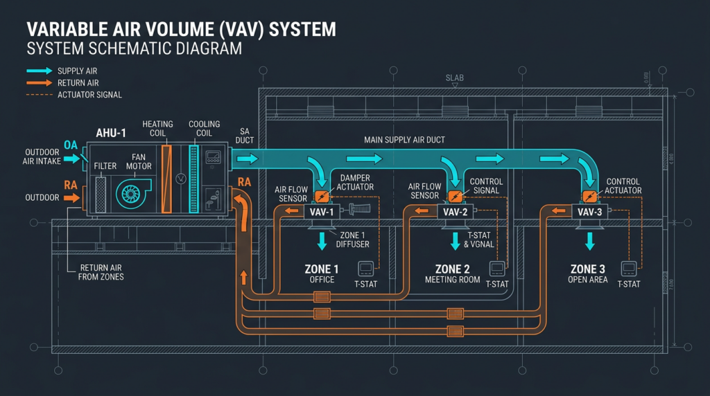
A VAV system conditions air centrally and distributes it through a network of ducts to individual building zones. The defining characteristic is that supply air temperature remains relatively constant while the volume of air delivered to each zone changes in response to thermal load. This stands in direct contrast to constant air volume (CAV) systems, which maintain a fixed airflow rate and vary the supply air temperature to meet demand.
Central Air Handling Unit
The air handling unit (AHU) serves as the heart of every VAV system. It draws in a mixture of outdoor air and recirculated return air, then conditions that air before sending it through the supply ductwork. A typical AHU contains the following components:
- Supply and return fans that move air through the system
- Cooling coils supplied with chilled water or direct expansion (DX) refrigerant
- Heating coils using hot water, steam, or electric resistance elements
- Filters rated at MERV 8 to MERV 16, depending on application requirements
- Mixing boxes that blend outdoor air with return air to meet ventilation requirements
- Humidifiers or dehumidifiers where humidity control is required
In cooling mode, the AHU typically supplies air at a constant temperature between 53°F and 57°F (12°C to 14°C). The supply air temperature setpoint may reset upward during mild weather or low-load conditions to save energy, a strategy known as supply air temperature reset.
VAV Terminal Units (VAV Boxes)
VAV boxes, also called terminal units, are installed in the ductwork serving each zone. Each box contains a modulating damper that opens or closes to regulate the volume of supply air entering the zone. When a zone needs more cooling, the damper opens wider. When the zone is satisfied, the damper throttles back to a minimum position. Several types of VAV boxes serve different needs:
- Single duct VAV boxes: The most common type. A single damper modulates airflow from the supply duct. Some include a reheat coil (hot water or electric) that activates when the zone requires heating, preventing overcooling at minimum airflow.
- Dual duct VAV boxes: These units receive air from separate hot and cold supply ducts and blend the two streams to achieve the desired discharge temperature. Once popular, dual duct systems are less common today due to higher duct installation costs and energy penalties from simultaneous heating and cooling.
- Fan-powered VAV boxes: These incorporate a small integral fan. In series fan-powered boxes, the fan runs continuously, drawing air from the return plenum and mixing it with primary supply air to maintain constant airflow to the zone. In parallel fan-powered boxes, the fan activates only during heating mode or when primary airflow drops below a setpoint, supplementing conditioned air with warm plenum air. Fan-powered boxes are especially useful in perimeter zones where heating loads can be significant.
Thermostats and the Control System
Each zone contains a thermostat or temperature sensor that continuously monitors space conditions. When the measured temperature deviates from the setpoint, the thermostat sends a signal to the VAV box controller, which repositions the damper and, if present, activates the reheat coil. Modern VAV systems rely on Direct Digital Control (DDC) systems integrated into a Building Automation System (BAS). The BAS provides centralized monitoring, scheduling, trend logging, alarm management, and remote access, enabling facility managers to optimize performance across the entire building from a single interface.
Static Pressure Control
As VAV boxes open and close throughout the building, the pressure in the supply ductwork fluctuates. Maintaining stable duct static pressure is critical. A pressure sensor located approximately two-thirds of the way down the longest duct run measures static pressure and sends that reading to the AHU controller. The controller adjusts the supply fan speed through a variable frequency drive (VFD) to maintain the static pressure setpoint, typically between 1.0 and 2.0 inches of water gauge (in. w.g.). Without proper static pressure control, the system suffers from damper hunting, inconsistent zone temperatures, excessive noise, and wasted fan energy.
Technical Specifications and Performance Parameters
Airflow Measurement
Accurate airflow measurement at each VAV box is essential for maintaining comfort and meeting ventilation codes. Common measurement methods include:
- Differential pressure sensors paired with flow crosses or flow rings built into the VAV box inlet
- Pitot tube arrays for larger duct sections
- Thermal (hot-wire) anemometers in some advanced terminal units
- Ultrasonic flow meters gaining adoption in newer installations for their low pressure drop and high accuracy
Typical factory-calibrated accuracy for VAV box airflow sensors falls within plus or minus 5% of reading down to the minimum controllable airflow. Poor sensor accuracy leads to over-ventilation, energy waste, and comfort complaints.
Pressure Drop Considerations
Every component in the air distribution path adds resistance. VAV boxes typically introduce 0.15 to 0.50 in. w.g. of pressure drop at design airflow, depending on size and configuration. Fan-powered boxes add slightly more due to their internal fan and mixing chamber. Minimizing total system pressure drop through proper duct sizing, smooth transitions, and low-loss fittings directly reduces fan energy consumption, which often represents the largest single energy cost in a VAV system.
Actuators
Damper actuators in VAV boxes come in three main types:
- Pneumatic actuators: Reliable and fast, but require a compressed air supply system. Common in older buildings.
- Electric actuators: Use small motors to drive the damper. Response times range from 60 to 90 seconds for full stroke. Low maintenance and no air supply needed.
- Electronic (direct-coupled) actuators: Mount directly to the damper shaft, eliminating linkages. They offer precise positioning, fast response (as low as 30 seconds full stroke), and integration with DDC controllers via analog or digital protocols.
Variable Frequency Drives
Variable frequency drives (VFDs) modulate fan speed to match real-time airflow demand. Because fan power varies with the cube of speed according to the fan affinity laws, reducing fan speed by 20% cuts power consumption by nearly 50%. VFDs are specified by voltage rating (typically 208V, 480V, or 600V), horsepower (ranging from fractional HP up to 500 HP or more for large AHUs), and control method (sensorless vector or volts-per-hertz). Payback periods for VFD retrofits on existing constant-speed fans often fall between one and three years.
Advantages and Disadvantages
Advantages
- Energy efficiency: By delivering only the airflow each zone requires, VAV systems can reduce fan energy by 30% to 60% compared to constant volume alternatives. Supply air temperature reset and optimal start/stop routines yield additional savings.
- Individual zone control: Occupants in different areas can maintain different temperature setpoints, accommodating varying internal loads from equipment, occupancy, and solar exposure.
- Improved thermal comfort: Gradual airflow adjustments prevent the abrupt temperature swings common in on/off cycling systems.
- Reduced noise: Fans operating at reduced speed during part-load conditions generate substantially less noise than constant-speed fans, improving the acoustic environment.
Disadvantages
- Higher first cost: VAV boxes, DDC controllers, VFDs, and additional sensors increase installed cost by 15% to 25% compared to a basic constant volume system of similar capacity.
- Design and commissioning complexity: Proper duct sizing, static pressure sensor placement, airflow balancing, and control sequence programming demand experienced engineers and commissioning agents.
- System instability risk: Undersized ductwork, incorrectly located pressure sensors, or poorly tuned control loops can cause oscillating dampers, pressure surges, and comfort failures.
- Minimum airflow constraints: Codes require minimum outdoor air ventilation rates per ASHRAE Standard 62.1. At very low loads, maintaining these minimums can result in overcooling or unnecessary reheat energy, partially offsetting efficiency gains.
Common Misconceptions
“VAV systems are always more efficient than constant volume systems.” Efficiency depends entirely on proper design, commissioning, and ongoing maintenance. A poorly tuned VAV system with stuck dampers, failed sensors, or incorrect control sequences can consume more energy than a well-maintained CAV system. Regular recommissioning is essential to sustain savings.
“VAV systems cannot provide adequate ventilation.” When designed to comply with ASHRAE Standard 62.1 and equipped with proper minimum airflow setpoints or demand control ventilation, VAV systems meet or exceed ventilation requirements. The key is correctly calculating zone-level ventilation needs and programming minimum airflow limits into the DDC system.
“All VAV boxes are the same.” Single duct, dual duct, and fan-powered boxes serve fundamentally different purposes. Selecting the wrong type for a given zone, such as using a cooling-only single duct box in a perimeter zone with high heating loads, leads to comfort problems and wasted energy.
Practical Applications
Commercial Office Buildings
VAV systems dominate the office building market. Open floor plans, conference rooms, server closets, and perimeter offices all have different load profiles that change throughout the day. VAV zoning allows each area to receive precisely the conditioning it needs. Occupancy sensors integrated with the BAS can further reduce airflow and energy use in unoccupied zones.
Educational Facilities
Schools and universities benefit from VAV systems because classrooms experience dramatic occupancy swings between class periods. CO2-based demand control ventilation (DCV) paired with VAV boxes adjusts outdoor air intake in real time, maintaining air quality during a packed lecture and saving energy in an empty room.
Healthcare Facilities
Hospitals require strict temperature, humidity, and pressurization control. VAV systems in healthcare settings often include HEPA filtration, pressure-independent VAV boxes, and redundant controls. Operating rooms, isolation rooms, and pharmacies each require dedicated airflow and pressure relationships that VAV technology can maintain with high precision.
Laboratories and Cleanrooms
Laboratory VAV systems coordinate supply airflow with fume hood exhaust to maintain room pressurization and prevent cross-contamination. Cleanroom applications demand extremely tight airflow tolerances and high air change rates, often 20 to 600 air changes per hour depending on ISO classification. VAV controls reduce energy use during unoccupied periods while preserving cleanliness standards.
Current Data and Post-2023 Developments
Updated Efficiency Standards
ASHRAE Standard 90.1-2022 and the 2024 International Energy Conservation Code (IECC) impose stricter fan power limitations and broader requirements for VFDs, supply air temperature reset, and optimized static pressure control. New construction projects increasingly must demonstrate compliance through detailed energy modeling, pushing designers toward higher-performance VAV components and tighter control sequences.
Advanced Control Strategies
Predictive control algorithms and machine learning models are entering commercial BAS platforms. These systems analyze weather forecasts, occupancy patterns, and historical load data to pre-position dampers and adjust fan speeds before loads arrive, reducing energy spikes and improving comfort response. Fault detection and diagnostics (FDD) software continuously monitors VAV box performance, flagging stuck dampers, sensor drift, and control loop issues before they become comfort complaints or energy drains.
Smart Building Integration
IoT-enabled sensors, cloud-based analytics dashboards, and mobile applications now allow facility teams to monitor and adjust VAV systems remotely. Open communication protocols such as BACnet/IP, BACnet Secure Connect (BACnet/SC), and Project Haystack tagging standards facilitate interoperability between VAV controllers, lighting systems, and enterprise platforms.
Refrigerant Transitions
AHUs with DX cooling coils are shifting from R-410A to low-GWP alternatives such as R-454B and R-32 in response to the AIM Act phase-down schedule. These refrigerants operate at slightly different pressures and require updated coil designs and safety classifications (A2L, mildly flammable), which affects AHU selection and mechanical room ventilation requirements in new VAV system installations.
Related Technologies
Constant Air Volume (CAV) systems remain appropriate for spaces with stable, uniform loads such as warehouses, some retail environments, and single-zone applications where the added cost and complexity of VAV controls are not justified.
Displacement ventilation delivers supply air at low velocity near floor level, allowing it to rise naturally as it absorbs heat from occupants and equipment. When paired with VAV control at the AHU, displacement ventilation can improve indoor air quality in the breathing zone while using less fan energy than overhead mixing systems.
Underfloor air distribution (UFAD) uses a raised access floor as a supply plenum. VAV diffusers in the floor provide individual zone control and allow easy reconfiguration as office layouts change, making UFAD popular in technology campuses and flexible workspaces.
Demand control ventilation (DCV) adjusts outdoor air intake based on real-time CO2 concentrations or occupancy counts. Integrating DCV with VAV boxes ensures each zone receives the correct amount of fresh air without over-ventilating during partial occupancy, yielding significant energy savings in spaces with highly variable occupancy such as auditoriums and conference centers.
Chilled beam systems, both active and passive, handle sensible cooling loads using ceiling-mounted heat exchangers supplied with chilled water. In hybrid configurations, a downsized VAV system handles ventilation and latent loads while chilled beams manage the bulk of sensible cooling, reducing duct sizes and fan energy.
Key Takeaways
- VAV systems control indoor climate by varying the volume of supply air to each zone while maintaining a relatively constant supply air temperature.
- The AHU, VAV terminal units, DDC controls, and VFDs work together as an integrated system. Weak performance in any one component undermines the whole installation.
- Energy savings of 30% to 60% over constant volume systems are achievable, but only with proper design, commissioning, and ongoing maintenance.
- Different VAV box types, including single duct, dual duct, and fan-powered units, address different zone requirements. Correct selection is critical.
- Emerging technologies such as predictive controls, FDD software, IoT integration, and low-GWP refrigerants are shaping the next generation of VAV system performance.
- VAV systems remain the workhorse of commercial HVAC. For anyone involved in building design, operation, or energy management, a thorough understanding of VAV principles is essential. Consult with qualified HVAC engineers to ensure that system design, installation, and control sequences align with current codes and best practices for your specific application.