HVAC electrical diagrams are the roadmaps that technicians, engineers, and informed homeowners use to understand how heating, ventilation, and air conditioning systems are wired and controlled. Without the ability to read these diagrams, safe troubleshooting is impossible, installations become guesswork, and maintenance turns into a liability. Every residential furnace, commercial rooftop unit, and industrial chiller ships with electrical diagrams attached to or inside the equipment panel. Learning to interpret them is a foundational skill for anyone who works on HVAC systems or wants to understand how their equipment operates.
Types of HVAC Electrical Diagrams
Not all electrical diagrams serve the same purpose. Three primary types exist in HVAC work, each offering a different perspective on the same system. Choosing the right diagram for the task at hand is the first step in effective troubleshooting or installation.
Ladder Diagrams (Schematic Diagrams)
Ladder diagrams are the most commonly used diagrams for understanding control logic in HVAC systems. They are drawn with two vertical lines representing the power rails (L1 and L2, or hot and neutral), with horizontal “rungs” connecting them. Each rung contains a load (such as a motor, relay coil, or solenoid valve) and the switches, contacts, or controls that govern it.
Ladder diagrams do not represent physical wire routing or component location. Their purpose is purely logical: they show the sequence in which circuits operate and how control devices interact. A thermostat calling for cooling, for example, energizes a relay coil on one rung, and the relay’s normally open contacts close on another rung to start the compressor. This cause-and-effect relationship is immediately visible in a well-drawn ladder diagram.
Key features of ladder diagrams include:
- Circuits are read left to right, top to bottom
- Each rung is an independent circuit path
- Control elements (switches, contacts, sensors) appear on the left side of each rung
- Loads (motors, coils, heaters) appear on the right side, closest to the L2 rail
- Series and parallel relationships between components are clearly visible
Wiring Diagrams (Pictorial Diagrams)
Wiring diagrams show the physical connections between components. They depict each wire, its color, its terminal designation, and the approximate physical location of components within the equipment. Unlike ladder diagrams, wiring diagrams are concerned with how things are actually connected rather than how the logic flows.
Technicians use wiring diagrams when they need to locate a specific wire at a terminal block, trace a wire through a conduit or harness, or verify that a physical connection matches the manufacturer’s specifications. These diagrams are invaluable for identifying broken wires, loose connections, and incorrect terminations. They often include wire color codes, connector types, and terminal numbers.
Block Diagrams
Block diagrams provide a high-level overview of a system. Each major component or subsystem is represented as a labeled rectangle, with lines showing the general flow of power and signals between them. Block diagrams are useful for gaining an initial understanding of a complex system before examining detailed schematics. They are common in documentation for building automation systems (BAS), variable frequency drives (VFDs), and multi-zone commercial equipment.
Electrical Symbols and Standards
ANSI Y32.2 Symbols
In the United States, electrical symbols used in HVAC diagrams follow the ANSI Y32.2 standard (also known as IEEE 315). This standard defines the graphical symbols for switches, motors, transformers, relays, capacitors, resistors, fuses, circuit breakers, and dozens of other components. Common HVAC-specific symbols include:
- Motors: A circle with the letter M or with specific markings indicating single-phase or three-phase operation
- Transformers: Two coils (or parallel lines) with a core between them, labeled with primary and secondary voltages
- Relays and contactors: A coil symbol (circle or rectangle) with associated contacts shown elsewhere in the diagram, linked by dashed lines or matching designations
- Normally open (NO) contacts: Two lines with a gap between them
- Normally closed (NC) contacts: Two lines with a diagonal line crossing the gap
- Capacitors: Two parallel lines (one curved for electrolytic types), labeled with microfarad (µF) and voltage ratings
- Fuses: A small S-curve or a link symbol between two connection points
- Circuit breakers: A line with a small rectangle or dot indicating the trip mechanism
- Thermostats: A switch symbol with a temperature-sensing element indicator
- Pressure switches: A switch symbol with an arc or pressure indicator
- Heating elements: A zigzag or rectangular resistor symbol
- Solenoid valves: A coil symbol connected to a valve body indicator
IEC 60617 Symbols
The IEC 60617 standard governs electrical symbols internationally. Technicians working on equipment manufactured in Europe or Asia may encounter IEC symbols, which differ from ANSI symbols in several ways. For example, IEC uses a filled rectangle for a resistor rather than the zigzag line common in ANSI diagrams. A motor is represented similarly but may include different internal markings. Familiarity with both standards is increasingly important as globally sourced equipment becomes more common in the North American market.
Voltage Levels in HVAC Systems
HVAC systems operate at multiple voltage levels, and diagrams must clearly distinguish between them. Misidentifying the voltage of a circuit is one of the most dangerous mistakes a technician can make.
- Low voltage (24 VAC): Powers control circuits including thermostats, relay coils, gas valve solenoids, and control boards. A step-down transformer converts line voltage to 24 VAC. This is the voltage present on thermostat wiring.
- Line voltage (120 VAC): Powers indoor blower motors in many residential systems, ignition controls, and auxiliary equipment.
- Line voltage (208 VAC, 240 VAC): Powers compressors, condensing unit fan motors, and electric heating elements in residential and light commercial equipment. Single-phase 240 VAC is standard for residential condensing units.
- Line voltage (480 VAC): Common in commercial and industrial HVAC systems. Often three-phase, powering large compressors, chillers, and air handling units.
Diagrams typically separate low-voltage control circuits from high-voltage power circuits. In ladder diagrams, different sections may be drawn for 24 VAC control and 240 VAC power, with the transformer clearly shown bridging the two.
Component Ratings and Nameplate Data
Electrical diagrams often reference component ratings that also appear on equipment nameplates. Understanding these ratings is essential for proper sizing, replacement, and code compliance.
- Motors: Rated by horsepower (HP), voltage, full load amps (FLA), locked rotor amps (LRA), phase (single or three), RPM, and service factor. FLA determines the size of circuit breakers and wire conductors per the National Electrical Code (NEC). LRA, which can be 5 to 8 times FLA, determines the rating needed for overcurrent protection during startup.
- Transformers: Rated by primary voltage, secondary voltage, and volt-ampere (VA) capacity. A typical residential HVAC transformer is 240V/24V at 40 VA.
- Contactors and relays: Rated by coil voltage (typically 24 VAC for HVAC contactors) and contact amperage for both resistive and inductive loads. Inductive load ratings are lower because of the higher inrush current associated with motors.
- Circuit breakers and fuses: Rated by amperage and ampere interrupting capacity (AIC). Proper AIC ratings prevent catastrophic failure during short circuit events.
- Capacitors: Rated in microfarads (µF) and voltage. Run capacitors in HVAC systems typically range from 5 µF to 80 µF at 370 VAC or 440 VAC.
Reading Ladder Diagrams Step by Step
To read a ladder diagram effectively, start at the top rung and work downward. Each rung represents a circuit that can be analyzed independently.
- Identify the power rails (L1 and L2) and the voltage they carry.
- Locate the transformer if the diagram includes both line-voltage and low-voltage sections.
- On each rung, identify the load on the right side. This is the component being controlled.
- Trace leftward from the load through all switches, contacts, and safety devices. Every one of these must be closed (or in the correct state) for current to flow through the load.
- Identify cross-references. When a relay coil is energized on one rung, its associated contacts change state on other rungs. These contacts are labeled with the same designation as the coil.
- Determine series and parallel relationships. Components in series must all be satisfied for current to flow. Components in parallel offer alternative paths for current.
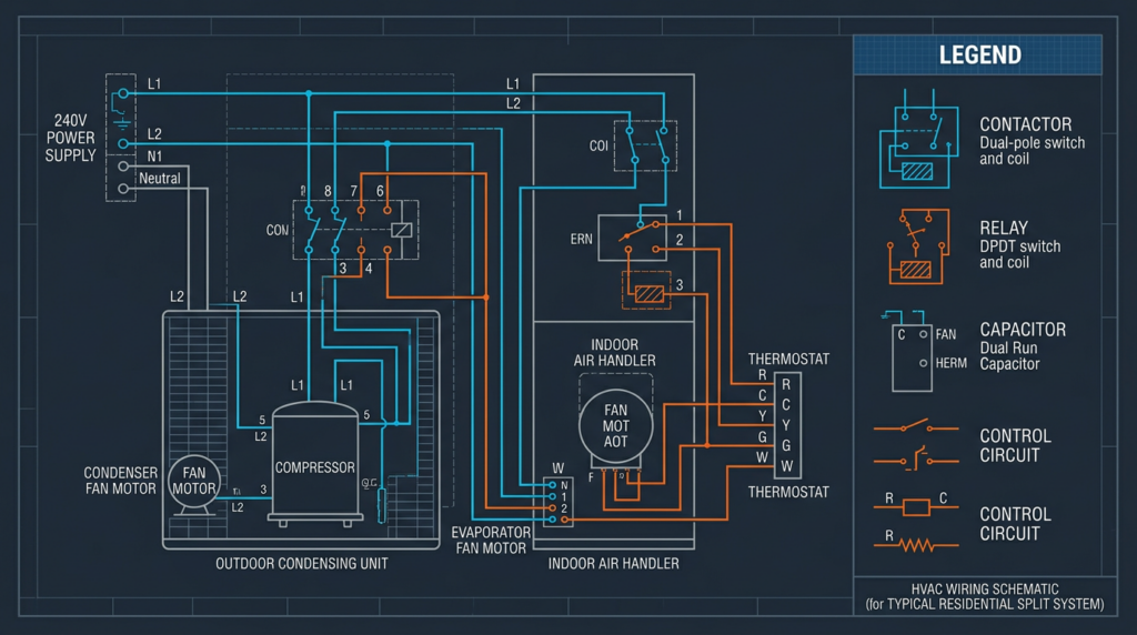
For example, in a basic cooling circuit: the thermostat closes on a call for cooling, energizing the Y terminal. This sends 24 VAC to the contactor coil. The contactor’s normally open contacts close, connecting 240 VAC to the compressor and condenser fan motor. Simultaneously, the G terminal energizes the indoor blower relay, starting the indoor fan.
Safety Devices in HVAC Diagrams
Safety devices appear throughout HVAC diagrams and must never be bypassed. Their positions in the circuit reveal what they protect and how they function.
- Thermal overloads: Wired in series with motor windings, these open the circuit if the motor draws excessive current, preventing burnout.
- High-pressure switches: Open on a rise in refrigerant pressure above a set point (typically 400 to 625 PSI for R-410A systems), shutting down the compressor to prevent catastrophic failure.
- Low-pressure switches: Open on a drop in refrigerant pressure below a set point, indicating a loss of charge or restricted airflow.
- Flame sensors: In gas furnaces, the flame sensor provides a microamp-level DC signal (typically 1 to 6 microamps) to the control board confirming burner ignition. Loss of this signal triggers an immediate gas valve shutdown.
- Limit switches: Temperature-activated switches in the supply air plenum that open if air temperature exceeds safe levels (typically 150 to 200 degrees Fahrenheit), shutting down the heat source while allowing the blower to continue running.
- Fuses and circuit breakers: Provide overcurrent protection for the entire system or individual circuits.
Thermostat Wiring and Terminal Designations
Thermostat wiring is one of the most common areas where diagram reading is applied. Standard thermostat terminal designations include:
- R: 24 VAC power (hot) from the transformer. Some systems split this into Rc (cooling) and Rh (heating).
- C: Common (24 VAC return). Required by most electronic and smart thermostats for continuous power.
- W: Heating call. Energizes the gas valve, oil burner, or electric heat relay.
- Y: Cooling call. Energizes the compressor contactor.
- G: Fan call. Energizes the indoor blower relay for fan-only operation.
- O/B: Reversing valve control for heat pump systems. O energizes in cooling (Carrier/Honeywell convention), B energizes in heating (Rheem convention).
Smart thermostats and communicating systems may use proprietary wiring or data bus connections. Always consult the manufacturer’s wiring diagram when installing these systems.
Advanced Topics
Three-Phase Power
Commercial and industrial HVAC systems commonly use three-phase power (208V, 460V, or 575V). Three-phase diagrams show three power lines (L1, L2, L3) and include components such as phase monitors, which protect equipment from phase loss or reversal. Motor wiring differs significantly from single-phase: three-phase motors have three or more leads, and their rotation direction depends on the phase sequence.
Variable Frequency Drives
Variable frequency drives (VFDs) control motor speed by varying the frequency and voltage of the power supplied to the motor. VFD diagrams include input power connections, DC bus components, output to the motor, and control signal wiring (0-10 VDC, 4-20 mA, or digital communication protocols like BACnet or Modbus). VFDs are increasingly common as SEER2 efficiency standards (effective January 1, 2023) drive wider adoption of variable-speed compressors and fans.
Refrigerant Transition Impacts
The AIM Act is phasing down HFC refrigerants including R-410A. Starting in 2025, production and import of R-410A for new equipment is being limited. Replacement refrigerants such as R-32 and R-454B are classified as A2L (mildly flammable), which introduces new safety requirements under UL 60335-2-40. Electrical diagrams for A2L-compatible equipment may include additional safety circuits such as refrigerant leak detection sensors, automatic shutoff valves, and ventilation interlocks. Technicians must be prepared to interpret these new circuit elements.
Building Automation and PLCs
Building automation systems (BAS) and programmable logic controllers (PLCs) add layers of complexity to HVAC electrical diagrams. These systems use digital and analog input/output modules, communication buses, and software-defined control sequences. Diagrams for BAS-integrated equipment include I/O point lists, communication wiring, and references to software programming rather than hardwired logic alone.
Safety Considerations
Working with HVAC electrical systems can be lethal. Before performing any electrical work, follow these principles:
- Always perform lockout/tagout (LOTO) procedures before servicing equipment.
- Use appropriate personal protective equipment (PPE), including insulated gloves rated for the voltage present.
- Verify zero energy state with a properly rated voltage tester before touching any conductors.
- Never assume a diagram is accurate. Field modifications, previous repairs, and installation errors can create discrepancies between the diagram and actual wiring. Verify everything.
- Only qualified personnel should perform electrical work on HVAC systems. Many jurisdictions require specific licensing.
Common Misconceptions
- Wire colors are always consistent: While conventions exist (red for 24 VAC hot, blue for common, yellow for cooling, white for heating, green for fan), older systems and field modifications frequently deviate. Always verify against the diagram and test with a meter.
- Voltage presence means the circuit works: A circuit can show correct voltage at one point but fail to deliver adequate current due to high resistance connections, damaged conductors, or failed components. Always measure amperage and check continuity as part of diagnosis.
- All diagrams are the same: Ladder diagrams, wiring diagrams, and block diagrams each serve distinct purposes. Using a wiring diagram to trace control logic is inefficient. Using a ladder diagram to find a physical wire location is impossible.
- Reading diagrams requires an engineering degree: Systematic training and practice enable technicians at all levels to read HVAC electrical diagrams effectively. The skill is built through repetition, not academic prerequisites.
Essential Tools for Electrical Diagnosis
- Digital multimeter: Measures voltage (AC and DC), resistance (ohms), amperage, and capacitance. The single most important diagnostic tool.
- Non-contact voltage tester: Quickly confirms the presence or absence of voltage without direct contact.
- Clamp meter: Measures current draw without breaking the circuit. Essential for checking motor amperage against nameplate FLA.
- Wire strippers and crimpers: Required for making proper connections during repairs or installations.
- Manufacturer documentation: Always obtain the correct diagram for the specific model and serial number. Manufacturer websites are the most reliable source.
Key Takeaways
HVAC electrical diagrams are essential tools for anyone who installs, maintains, or troubleshoots heating and cooling systems. Ladder diagrams reveal control logic. Wiring diagrams show physical connections. Block diagrams provide system overviews. Mastering all three types, along with a working knowledge of ANSI symbols, voltage levels, component ratings, and safety device functions, enables faster and safer diagnosis of problems ranging from a failed contactor (typically $150 to $400 to replace) to complex control board faults. As equipment grows more sophisticated with variable-speed technology, A2L refrigerant safety circuits, and BAS integration, the ability to read and interpret electrical diagrams becomes more critical with each passing year. Invest the time to learn this skill thoroughly, practice on real diagrams whenever possible, and never compromise on electrical safety.