Combustion analysis is the systematic measurement and evaluation of flue gas products from gas-fired appliances to determine operating efficiency, verify safe operation, and diagnose performance problems. Every gas furnace, boiler, and water heater produces byproducts when burning fuel, and those byproducts tell a detailed story about what is happening inside the appliance. A properly performed combustion analysis can reveal dangerous carbon monoxide levels, wasted energy, cracked heat exchangers, and venting failures before they become catastrophic. For HVAC technicians, combustion analysis is among the most important diagnostic skills in the trade. For homeowners, understanding this process explains why annual maintenance visits matter far beyond simple filter changes.
The Combustion Process: What Happens When Gas Burns
Combustion is a chemical reaction between a fuel and oxygen that produces heat. In a gas appliance burning natural gas (primarily methane, CH₄), the ideal or stoichiometric reaction is simple: one molecule of methane combines with two molecules of oxygen to produce one molecule of carbon dioxide (CO₂) and two molecules of water vapor (H₂O), plus heat energy.
In practice, perfect stoichiometric combustion never occurs inside an appliance. Burners require excess air beyond the theoretical minimum to ensure complete combustion. Too little excess air results in incomplete combustion, which produces carbon monoxide (CO), soot, and aldehydes. Too much excess air wastes energy by heating air that passes through the heat exchanger without contributing to the combustion reaction. The goal of combustion analysis is to verify that the appliance operates within the narrow band where combustion is complete, efficient, and safe.
Different fuels have different stoichiometric requirements. Natural gas requires approximately 10 cubic feet of air per cubic foot of gas. Propane (C₃H₈) requires roughly 24 cubic feet of air per cubic foot of gas. These differences affect ideal CO₂ levels, expected flue gas temperatures, and efficiency calculations.
Parameters Measured in Combustion Analysis
Oxygen (O₂)
Oxygen percentage in the flue gas is the primary indicator of excess air. In a perfectly sealed system burning natural gas with no excess air, O₂ in the flue would be 0%. In real-world operation, typical acceptable O₂ readings for natural gas range from 4% to 9%, corresponding to roughly 20% to 80% excess air. Readings below 4% suggest a rich condition with insufficient air, raising carbon monoxide risk. Readings above 9% indicate excessive dilution air, which reduces efficiency by carrying heat up the flue.
Carbon Dioxide (CO₂)
Carbon dioxide percentage reflects combustion completeness and is inversely related to excess air. The theoretical maximum CO₂ for natural gas is approximately 11.7%, and for propane approximately 13.8%. In practice, typical readings for a properly tuned natural gas appliance range from 8% to 10% CO₂. Higher CO₂ generally means less excess air and higher efficiency, but only when CO levels remain low. A high CO₂ reading paired with elevated CO indicates dangerous incomplete combustion rather than efficient operation.
Carbon Monoxide (CO)
Carbon monoxide is measured in parts per million (ppm) and is the single most critical safety parameter. CO is an odorless, colorless gas that can cause serious illness or death. ANSI Z21.47 (the standard for gas-fired central furnaces) specifies that CO in an air-free flue gas sample should not exceed 400 ppm under normal operating conditions. Many manufacturers set stricter internal limits, and most experienced technicians consider any reading above 100 ppm air-free as a condition requiring immediate investigation.
For water heaters, ANSI Z21.10.1 applies, and for boilers, ANSI Z21.13 sets the requirements. Each standard includes specific CO thresholds for the respective appliance type. Technicians must always consult the manufacturer’s specifications, as some high-efficiency appliances have much tighter acceptable ranges.
Stack Temperature (Flue Gas Temperature)
Stack temperature is the temperature of the flue gas measured at the breach or flue pipe. The net stack temperature is calculated by subtracting the ambient (room) temperature from the gross stack temperature. This net value is a key input for efficiency calculations. A conventional natural gas furnace typically has a stack temperature between 300°F and 500°F. A condensing furnace operates with stack temperatures below the dew point of the flue gases, typically 100°F to 130°F, which is why it extracts latent heat and achieves higher efficiency. An abnormally high stack temperature can indicate a dirty heat exchanger, oversized burner, or restricted airflow.
Draft
Draft is the pressure difference between the appliance vent connector and the surrounding air, measured in inches of water column (in. w.c.). Natural draft appliances typically require negative 0.02 to negative 0.05 in. w.c. in the vent connector to ensure proper exhaust flow. Induced draft and forced draft appliances have their own specifications. Insufficient draft can cause flue gas spillage into the living space. Excessive draft wastes energy and can cause flame instability. Draft measurements are taken with a manometer or a combustion analyzer equipped with a pressure sensor.
Nitrogen Oxides (NOx)
Nitrogen oxides are measured in ppm and have become increasingly important as air quality regulations tighten. California’s South Coast Air Quality Management District (SCAQMD) has led the way with Rule 1111, which limits NOx emissions from residential natural gas furnaces to 14 ng/J (approximately 20 ppm). Several other states are adopting similar standards. Not all combustion analyzers include NOx sensors, but technicians working in regulated areas need this capability.
Combustion Analyzers: Tools of the Trade
Types of Analyzers
Portable combustion analyzers are the workhorses of HVAC service. These handheld devices include a flue gas sampling probe, onboard sensors, a display screen, and built-in calculation software. They range from basic models measuring O₂, CO, and stack temperature to professional-grade units that add CO₂, NOx, draft, and differential pressure measurement. Prices range from approximately $300 to $500 for entry-level units, $800 to $1,500 for mid-range models, and $2,000 to $5,000 or more for full-featured professional analyzers from manufacturers like Testo, Bacharach, and UEi.
In-situ analyzers are permanently installed in commercial and industrial applications for continuous monitoring. These are less common in residential HVAC but are used in large boiler plants and industrial process heating.
Sensor Technology
Most portable analyzers use electrochemical sensors. These sensors generate a small electrical current proportional to the target gas concentration. They are accurate, affordable, and compact, but they degrade over time and require periodic replacement, typically every two to three years depending on usage and exposure. Infrared (NDIR) sensors are used in some higher-end analyzers, particularly for CO₂ measurement. Infrared sensors last longer and do not degrade like electrochemical cells, but they are more expensive.
Calibration and Maintenance
Regular calibration is essential for accurate readings. Most manufacturers recommend annual calibration using certified reference gases. Calibration costs typically range from $100 to $300 depending on the analyzer model and the number of sensors. Between calibrations, technicians should perform a fresh air zero before each use, replace intake filters regularly, and monitor sensor health indicators on the analyzer display. Sensors exposed to extremely high CO concentrations or corrosive gases may need early replacement.
Performing a Combustion Analysis Test
Preparation
Before testing, the appliance must reach steady-state operating conditions. For furnaces, this typically means running for at least 10 minutes after the main burner ignites. All access panels must be in place, as removing panels on induced draft furnaces changes the pressure dynamics and skews results. The technician should verify that the thermostat is calling for heat and the blower is operating normally. Ambient temperature and barometric pressure should be noted, as they affect readings.
Probe Placement
The sampling probe must be inserted into the flue pipe downstream of the last heat exchanger section but upstream of any draft diverter or barometric damper. For Category I natural draft appliances, the probe is typically placed in the vent connector between the draft hood and the chimney. For Category IV condensing furnaces, the probe goes into the flue pipe after the secondary (condensing) heat exchanger. The probe tip should be positioned in the center of the flue gas stream, angled to face the direction of flow. A drilled hole with a sealable grommet provides the best access point.
Recording and Interpreting Results
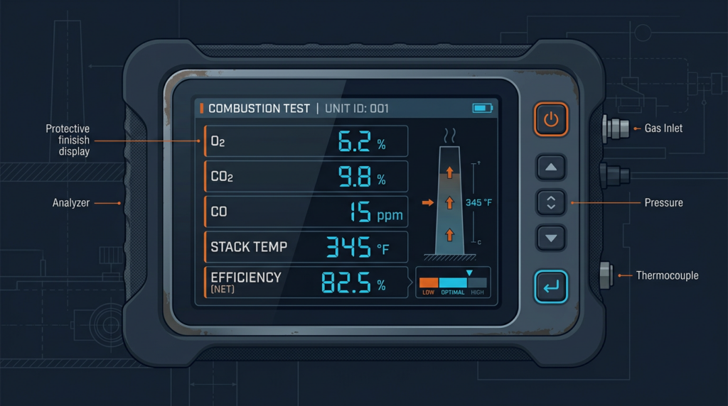
Once the analyzer stabilizes (usually 60 to 90 seconds after probe insertion), the technician records all parameters. A properly functioning natural gas furnace should show:
- O₂: 4% to 9%
- CO₂: 8% to 10%
- CO: below 100 ppm air-free (well below 400 ppm ANSI limit)
- Stack temperature: consistent with appliance type (300°F to 500°F for conventional, 100°F to 130°F for condensing)
- Draft: negative 0.02 to negative 0.05 in. w.c. for natural draft appliances
- Combustion efficiency: 78% to 82% for conventional 80 AFUE furnaces; 90% to 98% for condensing furnaces
Results outside these ranges require investigation and corrective action. The technician should always compare readings against the specific manufacturer’s published specifications for the appliance being tested.
Combustion Efficiency Calculations
Combustion analyzers calculate efficiency automatically, but understanding the underlying math helps technicians evaluate results critically. The most common method is the Siegert Formula, which estimates stack loss based on net stack temperature and flue gas composition:
Stack Loss (%) = A₁ / (CO₂%) × (Stack Temp − Ambient Temp)
The constant A₁ is fuel-specific: approximately 0.636 for natural gas, 0.595 for propane, and 0.560 for No. 2 fuel oil. Combustion efficiency equals 100% minus the stack loss percentage.
A critical distinction exists between gross efficiency (based on Higher Heating Value or HHV) and net efficiency (based on Lower Heating Value or LHV). HHV includes the latent heat in the water vapor produced by combustion. LHV excludes it. In the United States, the Annual Fuel Utilization Efficiency (AFUE) rating uses HHV as its basis. A condensing furnace rated at 96% AFUE is 96% efficient on an HHV basis. On an LHV basis, the same furnace would appear to exceed 100% efficiency because it recovers some latent heat that LHV calculations do not include in the fuel energy content. Technicians must ensure their analyzer is set to the correct efficiency basis for meaningful comparisons.
Troubleshooting with Combustion Analysis
Combustion analysis data points directly to specific appliance problems:
- High CO with low O₂ and high CO₂: Rich combustion condition. Possible causes include a dirty or clogged air intake, oversized gas orifice, or excessive gas pressure. Check manifold pressure and clean the burner assembly.
- High CO with high O₂: This seemingly contradictory reading can indicate flame impingement, a cracked heat exchanger, or severe burner misalignment where some flames are starved for air while others receive too much.
- Elevated stack temperature: Dirty heat exchanger surfaces, restricted airflow across the heat exchanger (dirty filter, undersized ductwork, closed registers), or a blower motor running at incorrect speed.
- Positive draft on a natural draft appliance: Blocked or undersized chimney, competing exhaust devices depressurizing the building, or outdoor wind conditions causing downdraft. This is a serious spillage risk.
- High O₂ with low CO₂ and low efficiency: Excessive excess air, possibly caused by a cracked heat exchanger allowing combustion air to bypass the burner, a leaking vent connector, or an oversized draft hood.
Safety Considerations
Carbon monoxide is responsible for approximately 420 deaths and over 100,000 emergency room visits annually in the United States, according to CDC data. Combustion analysis is the only reliable method to quantify CO production in a gas appliance. Visual flame inspection alone cannot detect dangerous CO levels. A blue flame does not guarantee safe CO concentrations, and appliances can produce lethal amounts of CO while appearing to operate normally.
Technicians performing combustion analysis should carry a personal CO monitor, ensure adequate ventilation in the work area, and use appropriate personal protective equipment. If CO levels exceed safe thresholds, the appliance should be shut down immediately and the customer informed of the hazard before any repair is attempted.
Regulatory Landscape and Industry Standards
The U.S. Department of Energy (DOE) sets minimum efficiency standards for residential heating equipment. As of 2023, the DOE requires a minimum 80 AFUE for non-weatherized gas furnaces in southern states and 90 AFUE in northern states. Gas-fired hot water boilers must meet a minimum 84 AFUE. The Inflation Reduction Act (IRA) of 2022 provides tax credits of up to $600 for high-efficiency gas furnaces meeting 97 AFUE or higher under the Energy Efficient Home Improvement Credit (Section 25C), along with additional rebates through the Home Efficiency Rebate programs. These incentives are driving demand for high-efficiency condensing appliances that require precise combustion tuning.
ACCA Standard 5 (HVAC Quality Installation Specification) and ACCA Standard 9 (HVAC Quality Maintenance) both reference combustion analysis as part of proper installation verification and ongoing maintenance. NATE certification and HVAC Excellence certification both test technicians on combustion analysis principles and procedures.
Combustion Analysis in Hybrid and Dual Fuel Systems
As dual fuel heat pump systems become more common, combustion analysis remains essential for the gas heating component. In these systems, a heat pump provides primary heating until outdoor temperatures drop below a balance point, at which time the gas furnace takes over. Because the furnace may operate infrequently, combustion testing during annual maintenance is especially important. Components can deteriorate during long idle periods, and problems may not be apparent until the furnace runs under cold weather load. Technicians should perform a full combustion analysis on the gas side of any hybrid system during fall maintenance visits.
Practical Costs and Service Expectations
- Professional combustion analysis service call: $75 to $200, often included as part of an annual maintenance agreement
- Entry-level portable analyzer: $300 to $500
- Professional-grade analyzer: $1,500 to $5,000
- Annual calibration: $100 to $300
- Replacement electrochemical sensors: $75 to $250 per sensor
- Recommended testing frequency: Annually at minimum, after any repair affecting the burner or venting, and during initial commissioning of new equipment
Key Takeaways
Combustion analysis is not optional for responsible HVAC service. It is the only method that objectively quantifies appliance safety and efficiency. Visual flame inspection, while useful, cannot replace instrument-based measurement. Every gas appliance service call should include a combustion analysis, and results should be documented for the customer’s records and the technician’s liability protection. Properly calibrated instruments, correct probe placement, steady-state operating conditions, and comparison against manufacturer specifications are all essential for accurate results. With tightening efficiency standards, growing adoption of hybrid heating systems, and increasing regulatory attention to emissions, combustion analysis skills will only become more important for HVAC professionals in the years ahead.