Air handlers account for a significant portion of the energy consumed in residential and commercial HVAC systems, yet they remain one of the most misunderstood components in the conditioned air chain. An air handler is the indoor unit of a split HVAC system responsible for circulating conditioned air throughout a building. It is not a furnace, though it may contain heating elements. It is not simply an evaporator coil, though it houses one. An air handler is a complete assembly that filters, conditions, and distributes air using a blower, coils, filters, and controls housed within an insulated cabinet. This article provides a comprehensive breakdown of air handler components, types, and selection criteria, giving HVAC professionals and informed homeowners the technical foundation needed to specify, install, and maintain these essential units.
Air Handler Components
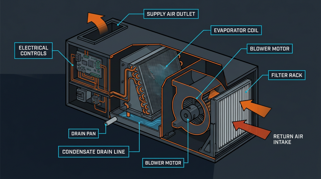
A modern air handler consists of several integrated subsystems, each playing a critical role in system performance. Understanding these components is essential for proper selection, installation, and troubleshooting.
Cabinet and Housing
The cabinet serves as the structural enclosure for all internal components. Most residential air handler cabinets are constructed from galvanized steel, though aluminum and composite materials appear in certain commercial and coastal applications where corrosion resistance is paramount. Powder-coated finishes have become increasingly common, extending cabinet life in humid environments.
Internal insulation reduces both thermal losses and operational noise. Fiberglass insulation (typically R-4 to R-8) and closed-cell foam insulation are the two most common options. Foam insulation offers superior moisture resistance and eliminates the risk of fiberglass particles entering the airstream. Access panels allow technicians to reach the blower, coils, and control board for service. Cabinet airtightness is critical: air leakage at seams and panel joints can reduce system efficiency by 5% to 15% and should be verified during commissioning, ideally in conjunction with duct leakage testing per ASHRAE or ACCA standards.
Blower and Fan Assembly
The blower is the heart of the air handler, responsible for moving conditioned air through the duct system. Three primary fan types are used in air handlers:
- Forward-curved fans: The most common type in residential units. They are compact and inexpensive but less efficient at higher static pressures.
- Backward-inclined fans: More efficient than forward-curved designs, these are common in commercial air handlers and perform well across a wider range of static pressures.
- Airfoil fans: The most efficient option, featuring aerodynamic blade profiles that reduce turbulence and noise. These are found in premium commercial units.
Motor type has a direct impact on energy consumption and comfort. PSC (Permanent Split Capacitor) motors operate at fixed speeds and are the least efficient option. ECM (Electronically Commutated Motor) motors offer variable-speed operation, adjusting airflow in response to system demand. ECM motors can reduce blower energy consumption by 60% to 80% compared to PSC motors, and their ability to ramp down to low speeds significantly improves dehumidification performance.
Blower capacity is rated in CFM (Cubic Feet per Minute). A typical residential system requires 400 CFM per ton of cooling capacity. Blower performance is directly affected by static pressure, which is the resistance to airflow created by ductwork, fittings, filters, and coils. Blower performance curves, provided by manufacturers, show CFM output at various static pressure levels, measured in inches of water column (in. w.c.). Most residential systems are designed for 0.5 in. w.c. total external static pressure, though actual field measurements often exceed this value due to poor duct design or restrictive filters.
Cooling and Heating Coils
The evaporator coil is where refrigerant absorbs heat from the indoor air during cooling mode. Most coils are constructed with copper tubes and aluminum fins, though aluminum microchannel coils are gaining market share due to lower refrigerant charge requirements and lighter weight. Microchannel coils can be more susceptible to corrosion in certain environments and are more difficult to repair if damaged.
Refrigerant metering at the coil is handled by either a TXV (Thermostatic Expansion Valve) or a fixed orifice. TXVs actively regulate refrigerant flow based on superheat, improving efficiency across a wider range of operating conditions and enhancing dehumidification. Most systems rated at 14 SEER or higher require a TXV for proper performance.
For heating, air handlers may include electric resistance heaters rated from 5 kW to 25 kW. These heaters typically operate in stages, with multiple elements energizing sequentially to prevent large inrush currents. Safety features include thermal cutout switches that de-energize the heaters if airflow drops below safe levels.
Air Filtration
The air filter protects internal components and improves indoor air quality. Filter performance is measured by the MERV (Minimum Efficiency Reporting Value) rating system:
- MERV 1 to 4: Basic fiberglass filters capturing particles larger than 10 microns (pollen, dust mites).
- MERV 5 to 8: Pleated filters capturing particles 3 to 10 microns (mold spores, pet dander).
- MERV 9 to 12: Higher-efficiency pleated filters capturing particles 1 to 3 microns (Legionella, lead dust).
- MERV 13 to 16: Hospital-grade filters capturing particles 0.3 to 1 micron (bacteria, tobacco smoke, some viruses).
Higher MERV ratings produce greater pressure drop across the filter, reducing available airflow. A clogged MERV 11 filter can add 0.3 to 0.5 in. w.c. of static pressure, significantly degrading system performance and increasing energy consumption. Filter replacement every 30 to 90 days is essential, depending on the filter type and environmental conditions.
Drain Pan and Condensate Management
During cooling, moisture condenses on the evaporator coil and collects in the drain pan. Pans are made from plastic or corrosion-resistant metal and must be properly sloped toward the drain outlet. A clogged condensate line is one of the most common causes of water damage and mold growth in HVAC systems. Where gravity drainage is not possible, a condensate pump is required. Float switches provide a safety shutoff, de-energizing the system if water levels rise above a safe threshold.
Control Panel
The control board manages all air handler operations, including thermostat signal interpretation, blower speed control, and staging of heating elements. Safety controls include high-pressure and low-pressure switches (in heat pump applications) and freeze protection sensors that shut down the system if coil temperatures drop below approximately 30°F to prevent ice formation.
Types of Air Handlers
Air handlers are classified by configuration, heating source, and blower control type. Selecting the correct type depends on installation location, system design, and comfort requirements.
Configuration Types
- Upflow: Air enters from the bottom and exits through the top. This is the most common configuration for basement and closet installations where ductwork runs overhead.
- Downflow: Air enters from the top and exits through the bottom. This configuration is used when ductwork runs beneath the unit, such as in slab-on-grade homes or attic installations feeding downward.
- Horizontal: Air enters one side and exits the other. Horizontal units fit in tight spaces like attics, crawl spaces, and above-ceiling plenums where vertical clearance is limited.
- Multipoise: These versatile units can be installed in upflow, downflow, or horizontal orientations, simplifying inventory for contractors and accommodating a wider range of installation scenarios.
Heating Source Classification
- Electric air handlers use resistance heating elements and are common in mild climates or as supplemental heat in heat pump systems.
- Hydronic air handlers contain a hot water coil connected to a boiler, common in commercial buildings and high-end residential applications.
- Heat pump compatible air handlers are designed to work with an outdoor heat pump for both heating and cooling, often including electric backup heat strips for use during defrost cycles or extreme cold.
- Furnace-integrated coil assemblies (often called “A-coils” or “cased coils”) mount on top of or inside a gas furnace. These are not standalone air handlers because the furnace provides the blower and heating; the coil assembly adds cooling capability only.
Blower Control Classification
- Single-speed: The blower operates at one fixed speed. Simple and inexpensive but offers no ability to adjust airflow for varying conditions.
- Multi-speed: The blower can operate at two to four preset speeds, selected by the installer or control board. This provides some flexibility but limited precision.
- Variable-speed (ECM): The blower continuously adjusts its speed to maintain target airflow regardless of changing static pressure. Variable-speed units deliver superior comfort, quieter operation at low speeds, and dramatically better dehumidification because the slower airflow allows more moisture to condense on the evaporator coil.
Modular Air Handlers
Modular air handlers are assembled from interchangeable sections, allowing engineers to specify exact combinations of coils, blowers, filters, mixing boxes, and energy recovery wheels. This approach dominates commercial applications where each building has unique airflow, heating, cooling, and ventilation requirements. Modular units can range from 1,000 CFM to over 100,000 CFM.
Air Handler Selection Criteria
Choosing the right air handler requires careful evaluation of multiple factors. Incorrect selection leads to comfort problems, energy waste, and premature equipment failure.
Capacity Matching
Air handler capacity must match the outdoor unit. Cooling capacity is measured in BTUH (British Thermal Units per Hour), and airflow must be correctly sized using a Manual J load calculation and Manual D duct design per ACCA standards. Oversizing causes short cycling, poor humidity control, and uneven temperatures. Undersizing results in the system running continuously without reaching setpoint. A properly sized system runs in longer, more efficient cycles.
Efficiency Ratings and AHRI Certification
Efficiency ratings like SEER (Seasonal Energy Efficiency Ratio) and HSPF (Heating Seasonal Performance Factor) apply to the complete matched system, not the air handler alone. An air handler paired with a non-certified outdoor unit may not achieve its rated SEER. Always verify compatibility through the AHRI (Air-Conditioning, Heating, and Refrigeration Institute) directory, which lists tested and certified equipment combinations. Current DOE minimum standards require 15 SEER2 for split-system air conditioners and 8.8 HSPF2 for heat pumps in most regions.
Static Pressure and Duct System Design
The air handler blower must overcome the total external static pressure of the duct system. Measure static pressure at the supply and return plenums using a manometer. If the duct system imposes 0.7 in. w.c. and the air handler blower is rated for only 0.5 in. w.c. at the required CFM, airflow will be insufficient. Proper duct sizing per Manual D is essential to keep static pressure within the air handler’s performance range.
Electrical Requirements
Air handlers require dedicated electrical circuits. Common residential configurations are 208/230V single-phase for blower operation and a separate circuit for electric heat strips, which may draw 30 to 60 amps depending on wattage. Verify voltage, amperage, and breaker sizing against the unit’s nameplate data before installation.
Noise Considerations
Air handler noise varies significantly by blower type and motor speed. Variable-speed ECM units operating at low speed can produce sound levels below 55 dB, while single-speed PSC units may exceed 70 dB. Cabinet insulation quality, vibration isolation mounts, and duct connections (flex duct transitions reduce noise transmission) all affect perceived noise levels in occupied spaces.
Installation Space and Accessibility
Verify physical dimensions against the available installation space, including required clearances for service access. Most manufacturers require 24 to 36 inches of clearance in front of the access panel and adequate room for filter removal. Closet installations need proper return air pathways and combustion air provisions if gas appliances share the space.
Budget and Long-Term Cost
A variable-speed air handler may cost $500 to $1,500 more than a single-speed equivalent, but the energy savings from the ECM motor and improved comfort often recover that premium within three to five years. Utility rebates and manufacturer incentives for high-efficiency equipment can further offset upfront costs.
Common Misconceptions
Several persistent myths lead to poor purchasing decisions and suboptimal system performance:
- “Any air handler works with any outdoor unit.” This is false. Mismatched systems may use incompatible refrigerants, have mismatched capacities, and will not achieve rated efficiency. Always consult the AHRI directory for approved combinations.
- “Bigger is always better.” An oversized air handler short cycles, fails to dehumidify properly, and wastes energy. Proper Manual J load calculations prevent this problem.
- “All air filters are the same.” A MERV 1 fiberglass filter and a MERV 13 pleated filter differ enormously in particle capture efficiency. The right filter depends on occupant health needs, system airflow capacity, and maintenance frequency.
- “Air handlers don’t need maintenance.” Neglected air handlers develop dirty coils (reducing capacity by 20% to 40%), clogged drains, and failing motors. Annual professional maintenance and regular filter changes are essential.
- “Variable-speed blowers don’t save money.” Field studies consistently show 30% to 50% reductions in blower energy consumption with ECM motors compared to PSC motors, along with improved comfort and humidity control.
Practical Applications and Troubleshooting
Air Balancing
Air balancing ensures that each room receives the correct volume of conditioned air. Use balancing dampers in branch duct runs to adjust airflow. Measure supply register CFM with a flow hood and compare against Manual D design values. Imbalanced airflow creates hot and cold spots, increases energy consumption, and generates pressure imbalances that drive infiltration.
Troubleshooting Common Problems
- No airflow: Verify power at the disconnect and breaker panel. Check the control board for fault codes. Test the blower motor capacitor (PSC motors) or check ECM motor wiring and communication signals.
- Insufficient airflow: Inspect the filter for excessive loading. Check for collapsed flex duct, closed dampers, or dirty evaporator coils. Verify blower speed settings against design requirements.
- Water leaks: Clear the condensate drain line using compressed nitrogen or a wet/dry vacuum. Inspect the drain pan for cracks. Verify that the condensate pump operates and the float switch functions properly.
- Excessive noise: Check for loose set screws on the blower wheel, worn motor bearings, or debris inside the cabinet. Vibration isolation pads can reduce noise transmitted to the building structure.
Preventative Maintenance Checklist
- Replace or clean the air filter every 30 to 90 days.
- Clean the evaporator coil annually using a no-rinse coil cleaner or water rinse as needed.
- Flush the condensate drain line with a mixture of water and vinegar or bleach quarterly.
- Inspect the drain pan for cracks, corrosion, and proper slope.
- Verify blower wheel cleanliness and motor operation.
- Check all electrical connections for tightness and signs of overheating.
- Test the condensate float switch and safety controls.
- Verify thermostat calibration and control board operation.
Smart Home Integration
Modern air handlers with ECM motors and communicating control boards integrate readily with smart thermostats and building automation systems. Platforms like Ecobee, Nest, and manufacturer-specific communicating systems (such as Carrier Infinity or Trane ComfortLink) allow remote monitoring of blower speed, filter status, and fault codes, enabling proactive maintenance and real-time performance optimization.
Related Topics and Future Trends
Air handler performance depends heavily on the quality of the connected duct system. Poorly designed or installed ductwork can negate the benefits of even the most advanced air handler. Zoning systems with motorized dampers allow a single air handler to independently condition multiple areas, improving comfort and reducing energy waste. On the indoor air quality front, integrated UV-C germicidal lamps, bipolar ionization devices, and high-MERV filtration racks are increasingly available as factory-installed options. Looking ahead, smart air handlers with onboard sensors for temperature, humidity, particulate count, and refrigerant pressure will enable predictive maintenance and fully automated performance optimization, further reducing energy consumption and improving occupant comfort.
Key Takeaways
The air handler is far more than a simple fan in a box. It is a precision assembly whose performance depends on correct component selection, proper system matching, and consistent maintenance. Always verify AHRI-certified matched system combinations to ensure rated efficiency. Size the system based on Manual J load calculations, not rules of thumb. Invest in variable-speed ECM technology for superior comfort, humidity control, and long-term energy savings. Maintain the unit diligently, with particular attention to filter replacement, coil cleanliness, and condensate drainage. When in doubt, consult a qualified HVAC professional who can perform accurate load calculations, verify duct system design, and ensure that the selected air handler meets the specific requirements of the building and its occupants.