What Fan Laws Are and Why They Matter
Fan laws are a set of proportional relationships that predict how changes in fan speed or air density affect three critical performance variables: airflow, pressure, and power consumption. Derived from the affinity laws of fluid dynamics and the principle of dynamic similarity, they give HVAC engineers, technicians, and informed building owners a reliable shortcut for estimating the consequences of adjusting a fan’s operating conditions without running a full new set of tests.
Understanding fan laws is essential for selecting the right fan, sizing variable frequency drives, troubleshooting airflow problems, and cutting energy costs. A small increase in fan speed, for example, produces a disproportionately large increase in power draw. Ignoring that cubic relationship has led to countless blown budgets and overloaded motors. These laws appear throughout ASHRAE Handbook fundamentals, AMCA certification standards, and everyday field work. They are approximations, not absolutes, but when applied correctly within their limits they are remarkably useful.
Core Variables and Units
Before examining the equations, it helps to define the variables clearly:
- Airflow (Q): The volume of air a fan moves per unit of time. Measured in cubic feet per minute (CFM) in IP units or cubic meters per second (m³/s) in SI.
- Pressure (P): The resistance the fan overcomes or the energy it imparts to the air. Measured in inches of water gauge (in. w.g.) or Pascals (Pa).
- Fan Speed (N): Rotational velocity of the impeller. Measured in revolutions per minute (RPM).
- Power (HP or W): The mechanical power input required to drive the fan. Measured in horsepower (HP) or watts (W).
- Air Density (ρ): Mass per unit volume of the air being moved. Measured in pounds per cubic foot (lb/ft³) or kilograms per cubic meter (kg/m³). Standard air density at sea level and 70 °F is approximately 0.075 lb/ft³ (1.2 kg/m³).
Pressure Types
Fan performance involves three pressure measurements. Static pressure (SP) is the pressure exerted uniformly in all directions within the duct, representing the energy available to push air through the system. Velocity pressure (VP) is the kinetic energy component, proportional to the square of air velocity. Total pressure (TP) is the sum of static and velocity pressure. Fan curves may be plotted against either static or total pressure, so knowing which one a manufacturer reports is critical for accurate comparisons. AMCA Standard 210 requires testing and reporting conventions that distinguish between these values.
The Three Speed Laws
When air density remains constant and only fan speed changes, three proportional relationships apply. These are the most frequently used fan laws in HVAC practice.
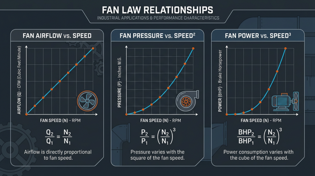
Law 1: Airflow Is Proportional to Speed
Q₂ / Q₁ = N₂ / N₁
If you increase fan speed by 20%, airflow increases by 20%. Double the speed, double the airflow. The relationship is linear and intuitive.
Law 2: Pressure Is Proportional to the Square of Speed
P₂ / P₁ = (N₂ / N₁)²
A 20% speed increase raises the pressure by a factor of 1.2² = 1.44, or 44%. This squared relationship means pressure climbs faster than airflow as speed rises.
Law 3: Power Is Proportional to the Cube of Speed
HP₂ / HP₁ = (N₂ / N₁)³
Here is where the math gets serious. That same 20% speed increase drives power up by 1.2³ = 1.728, or nearly 73%. Reducing speed by just 20% cuts power to 0.8³ = 0.512, a 49% reduction. This cubic relationship is the single most important reason variable speed fans save so much energy.
The Density Laws
When fan speed stays constant but air density changes, a second set of relationships governs performance. These are critical at high altitudes, in heated or cooled air streams, and in industrial processes with non-standard gas mixtures.
- Airflow (volume): Q₂ / Q₁ = ρ₁ / ρ₂. Volumetric airflow is inversely proportional to density. If air becomes less dense, the fan moves more volume (but less mass) at a given speed.
- Pressure: P₂ / P₁ = ρ₂ / ρ₁. Pressure developed by the fan is directly proportional to air density. At 5,000 feet elevation, where density drops roughly 17% compared to sea level, the fan produces about 17% less pressure.
- Power: HP₂ / HP₁ = ρ₂ / ρ₁. Power required is also directly proportional to density.
A common field scenario: a building in Denver, Colorado (elevation approximately 5,280 feet, air density roughly 0.062 lb/ft³) needs the same mass flow rate as an identical system at sea level. Because the fan develops less pressure per revolution, the designer must either select a larger fan or increase speed. This adjustment must be calculated using the density correction factors above, or the system will underperform.
System Curves and the Operating Point
A fan does not operate in isolation. Every duct system has a system resistance curve, which plots the pressure drop across the system as a function of airflow. For turbulent flow in ducts (the norm in HVAC), this curve follows a roughly squared relationship: doubling airflow quadruples the pressure drop.
The operating point is where the fan performance curve and the system resistance curve intersect. At this point, the pressure the fan produces exactly matches the pressure the system demands, and the resulting airflow is what the system actually delivers.
When fan speed changes, the entire fan curve shifts. Increasing speed shifts it up and to the right, producing more airflow at higher pressure. The new operating point moves along the system curve. Fan laws predict where the new operating point will land, making them indispensable for system balancing and VFD programming.
Variable Frequency Drives and Energy Savings
A variable frequency drive (VFD) adjusts the electrical frequency supplied to an AC motor, controlling its speed continuously. VFDs are the primary technology through which the cubic power law translates into real-world energy savings.
Consider a supply air handler rated at 10,000 CFM and 5 HP at full speed. If occupancy-based control allows the fan to run at 80% speed during partial-load conditions, the power drops to approximately 0.8³ × 5 HP = 2.56 HP. Over thousands of operating hours per year, those savings are substantial. The Department of Energy estimates that fan systems account for roughly 15% of all electricity consumed in U.S. commercial buildings, making speed reduction one of the most effective single energy conservation measures available.
Practical considerations for VFD installations include:
- Motor compatibility: Inverter-duty motors are preferred. Standard motors can overheat at low speeds because their internal cooling fans slow down as well.
- Minimum speed limits: Most fan and motor combinations have a practical minimum speed, often around 20% to 30% of full speed, below which motor cooling becomes inadequate or airflow sensors lose accuracy.
- Harmonic distortion: VFDs generate electrical harmonics that can affect other equipment on the same circuit. Line reactors or harmonic filters may be required.
- Cost: VFDs for typical HVAC fan motors (1 HP to 25 HP) range from approximately $400 to $3,500 installed, depending on motor size, enclosure type, and required accessories.
Fan Curves and Certified Performance Data
Reputable fan manufacturers publish fan curves generated through laboratory testing in accordance with AMCA Standard 210. These curves plot airflow against static or total pressure, brake horsepower, and efficiency for a given fan at a specific RPM and standard air density.
When a fan carries the AMCA Certified Ratings Program seal, it means an independent lab has verified that the published performance data are accurate. This certification is essential because the fan laws are only as good as the baseline data. Applying a speed-change ratio to inaccurate catalog data produces inaccurate predictions.
Key elements to read on a fan curve:
- The peak efficiency point, where the fan converts the most input power into useful airflow and pressure.
- The surge or stall region on the left side of the curve, where airflow is low and performance becomes unstable.
- The power curve, which shows whether the fan is a non-overloading type (power peaks and then decreases) or an overloading type (power continues to rise with airflow).
System Effect: The Hidden Performance Penalty
System effect is the loss of fan performance caused by non-ideal airflow conditions at the fan inlet or outlet. Fan laws assume smooth, uniform airflow entering and leaving the fan. In practice, elbows close to the fan inlet, abrupt transitions, obstructions, or missing duct sections create turbulence and flow distortion that reduce effective fan capacity.
AMCA Publication 201, “Fans and Systems,” provides system effect factors that quantify these losses. A common example: placing a 90-degree elbow directly at a centrifugal fan inlet without a straight duct run can reduce effective fan capacity by 10% to 25%, depending on the configuration. When applying fan laws to predict performance after a speed change, the engineer must account for system effect separately. The laws themselves do not compensate for it.
Limitations and Common Misconceptions
Fan laws are powerful tools, but misusing them leads to errors. The most important limitations include:
- They are approximations, not exact equations. They assume constant fan efficiency across the speed range. In reality, efficiency varies with operating point.
- They require geometric similarity. Changing blade pitch, impeller diameter, or housing geometry invalidates the relationships. The laws apply to the same fan at different speeds or the same fan in different density conditions.
- Accuracy degrades with large changes. The laws are most reliable for speed changes of roughly ±25% from the tested condition. Beyond that range, efficiency shifts and flow regime changes introduce meaningful error.
- They apply best to centrifugal and axial fans. Cross-flow fans, regenerative blowers, and positive-displacement blowers follow different performance characteristics.
- Flow regime matters. The laws assume fully turbulent flow. At very low speeds or in very small duct systems, flow may transition toward laminar conditions, breaking the squared pressure-to-speed relationship.
Practical Applications
Fan Selection
During design, an engineer calculates the required airflow (CFM) and system pressure drop (in. w.g.) based on duct layout, coil resistance, filter resistance, and diffuser drops. Using manufacturer fan curves, the engineer selects a fan that operates near peak efficiency at the design point. If the exact cataloged speed does not match, fan laws allow interpolation to a nearby speed. For example, a Greenheck centrifugal inline fan model SQ-180 might be listed at 1,150 RPM delivering 8,500 CFM at 2.0 in. w.g. If the project needs 7,500 CFM, the engineer calculates the target speed as 1,150 × (7,500 / 8,500) = 1,015 RPM and verifies the pressure and power at that speed.
Troubleshooting
A technician measuring only 80% of design airflow can use fan laws to check whether the fan is simply running at the wrong speed. If RPM is correct but airflow is low, the problem lies in the system: clogged filters, collapsed duct liner, closed dampers, or excessive system effect. Fan laws provide the expected baseline that field measurements are compared against.
Energy Optimization
Building operators use the cubic power law to justify VFD retrofits. If a constant-volume system currently runs a 15 HP fan at full speed but could meet loads at 70% speed for 60% of operating hours, the power at reduced speed is 0.7³ × 15 HP = 5.1 HP. At an average electricity cost of $0.12/kWh, the annual savings can exceed $4,000, often producing a VFD payback period of two to three years.
System Balancing
Testing, adjusting, and balancing (TAB) technicians use fan laws when adjusting sheave sizes on belt-driven fans. Changing the motor sheave diameter changes the fan RPM in direct proportion. The laws then predict the resulting airflow and confirm that motor amperage will remain within nameplate ratings.
Regulatory Context
The U.S. Department of Energy finalized rules establishing minimum fan efficiency grades (FEG) for commercial and industrial fans, with enforcement phased in starting in 2023 and 2024. These rules reference AMCA Standard 208 and set minimum efficiency requirements based on fan type and size. Selecting fans that exceed the DOE minimum efficiency threshold not only ensures code compliance but also amplifies the energy savings predicted by the cubic power law.
The Inflation Reduction Act of 2022 includes provisions for high-efficiency HVAC equipment and building energy improvements. While direct fan-only incentives are limited, VFD installations that reduce whole-building energy consumption may qualify under Section 179D commercial building deductions or utility rebate programs aligned with IRA funding.
As SEER2 testing protocols for air conditioners and heat pumps now include higher external static pressure requirements (0.5 in. w.g. for ducted systems), proper fan selection and accurate application of fan laws become even more important for meeting rated system efficiency in the field.
Key Takeaways
- Fan laws relate airflow linearly to speed, pressure to the square of speed, and power to the cube of speed. The cubic power relationship is the foundation of variable-speed energy savings.
- Air density corrections are essential at elevations above 2,000 feet or when air temperature differs significantly from 70 °F.
- System effect, non-ideal duct connections, and changing fan geometry all limit the accuracy of fan law predictions. Always account for these factors in real installations.
- Fan laws are most accurate for speed changes within about ±25% of a tested operating point and for centrifugal and axial fan types.
- Certified fan performance data from AMCA-tested products provides the reliable baseline that fan laws require. Never apply the laws to unverified or estimated catalog data.
- VFDs paired with the cubic power law routinely deliver 30% to 50% reductions in annual fan energy consumption in commercial HVAC systems, often paying for themselves within two to four years.