What Are HVAC Mechanical Plans?
HVAC mechanical plans are technical drawings that document the design, layout, and specifications of heating, ventilation, and air conditioning systems within a building. These drawings communicate the engineer’s design intent to everyone involved in construction, installation, maintenance, and inspection. They show where equipment goes, how ductwork and piping are routed, what controls govern system operation, and what performance standards the system must meet. For HVAC technicians, mechanical plans are the primary roadmap for installation and troubleshooting. For building owners, architects, and contractors, they provide essential context for coordinating trades, managing renovations, and verifying code compliance. The ability to read mechanical plans accurately prevents costly installation errors, reduces conflicts between building systems, and ensures that HVAC systems perform as designed.
Relationship to Other Construction Documents
Mechanical plans do not exist in isolation. They are part of a larger set of construction documents that includes architectural drawings (floor plans, reflected ceiling plans, building sections), structural drawings (framing, foundations), electrical drawings (power distribution, lighting), and plumbing drawings (water supply, waste). HVAC mechanical plans are typically overlaid on the architectural floor plan so that equipment locations, duct runs, and piping routes can be understood in relation to walls, ceilings, columns, and other building elements. Coordination between these disciplines is critical. A supply duct that conflicts with a structural beam or an electrical conduit creates field problems that cost time and money to resolve.
Types of Mechanical Plans
A complete mechanical drawing set for a commercial building may contain several distinct plan types, each serving a specific purpose.
- Floor plans with HVAC overlays show equipment locations, duct routing, and diffuser placements superimposed on the building’s architectural layout.
- Ductwork layouts provide detailed views of supply, return, and exhaust air distribution, including duct sizes, fittings, and airflow quantities at each branch and outlet.
- Piping schematics illustrate chilled water, hot water, refrigerant, and condensate piping systems, showing pipe sizes, valves, pumps, and flow directions.
- Control diagrams depict the building automation and control system, including sensors, controllers, actuators, and the logic sequences that govern system operation.
- Equipment schedules are tabular summaries listing every piece of HVAC equipment along with its capacity, model number, electrical requirements, and efficiency ratings.
Residential projects are typically simpler, often consisting of a single mechanical plan sheet with an equipment schedule and general notes. Large commercial and industrial projects may require dozens of mechanical sheets.
Essential Elements of HVAC Drawings
Symbols and Legends
Every mechanical plan includes a legend that defines the symbols used throughout the drawing set. While ASHRAE and ANSI publish standardized symbol libraries, individual engineering firms may use slight variations. Always refer to the project-specific legend before interpreting any drawing.
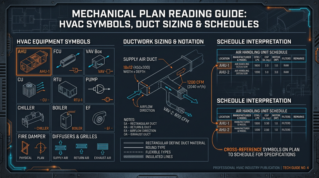
Common HVAC symbols represent the following:
- Air handling units (AHU), shown as rectangular boxes with fan and coil symbols inside
- Furnaces and boilers, represented by specific equipment symbols with flame indicators
- Diffusers, grilles, and registers, shown as squares or circles at duct termination points, often with airflow quantities (CFM) noted
- Dampers, including balancing dampers (manual adjustment), fire dampers (rated for fire separation), and smoke dampers (controlled by fire alarm systems)
- Valves, with distinct symbols for gate valves, ball valves, check valves, butterfly valves, and control valves
- Pumps, typically shown as circles with triangular flow indicators
- Thermostats and sensors, represented by small symbols at their wall or duct mounting locations
Standard line types distinguish between different systems on the same drawing. Supply air ducts often use a solid heavy line, return air ducts use a dashed line, and exhaust air ducts use a different dash pattern. Chilled water supply (CHWS), chilled water return (CHWR), hot water supply (HWS), and hot water return (HWR) piping each have unique line conventions, frequently using a combination of dashes, dots, and letter designations placed along the line.
Abbreviations and Terminology
Mechanical plans use a dense set of abbreviations. Some of the most common include:
- CFM: Cubic feet per minute (airflow rate)
- BTU/hr: British thermal units per hour (heating or cooling capacity)
- GPM: Gallons per minute (liquid flow rate)
- ESP: External static pressure (measured in inches of water column, or in. w.c.)
- FPM: Feet per minute (air velocity)
- AHU: Air handling unit
- VAV: Variable air volume
- VRF: Variable refrigerant flow
- RTU: Rooftop unit
- FCU: Fan coil unit
- MAU: Makeup air unit
Metric equivalents are common on international projects. Airflow may be stated in cubic meters per second (m³/s) or liters per second (L/s). Pressure is measured in Pascals (Pa). Capacity may be listed in kilowatts (kW) rather than BTU/hr.
Scales and Dimensions
Drawing scale defines the ratio between measurements on the plan and actual dimensions in the building. Common scales for HVAC floor plans are 1/8″ = 1′-0″ and 1/4″ = 1′-0″. Detail drawings of equipment rooms or complex assemblies may use larger scales such as 1/2″ = 1′-0″ or 3/4″ = 1′-0″. Always check the scale indicator on each sheet, as different sheets within the same set may use different scales. On digital plans viewed on screen, printed scale bars are more reliable than ruler measurements.
Notes and Specifications
General notes appear on one or more sheets and establish project-wide requirements such as applicable codes, insulation requirements, duct leakage testing standards, seismic bracing criteria, and references to ASHRAE Standard 90.1 or the International Energy Conservation Code (IECC). Specific notes are called out on individual drawings using numbered flags or keynotes, providing clarification for particular conditions. The written project specifications (typically a separate document organized by CSI MasterFormat divisions) supplement the drawings with detailed material and installation requirements.
Reading Ductwork Layouts
Ductwork Design Principles
Duct systems distribute conditioned air from equipment to occupied spaces and return air back to the equipment. Plans show three primary duct systems: supply air (conditioned air delivered to spaces), return air (air drawn back to the equipment for reconditioning), and exhaust air (air removed from the building, as from restrooms or kitchens). Duct sizing is driven by required airflow in CFM and acceptable static pressure losses. ACCA Manual D provides residential duct design procedures, while commercial systems rely on ASHRAE Fundamentals and the equal friction or static regain methods.
Identifying Ductwork Components
Plans show duct shapes and sizes. Rectangular ducts are noted with width x height dimensions (e.g., 24×12 means 24 inches wide by 12 inches tall). Round ducts are noted by diameter (e.g., 14″ dia.). Fittings include elbows (direction changes), tees (branch takeoffs), reducers (size transitions), and offsets. Each fitting creates pressure loss, so their quantity and type affect system performance.
Terminal devices are shown at the end of duct runs. Supply diffusers spread conditioned air into the room. Return grilles allow air to flow back toward the equipment. Registers are grilles with integral dampers for manual airflow adjustment. Each terminal device is typically labeled with its required airflow in CFM.
Analyzing Airflow Paths
To read a duct layout, start at the air handling unit or furnace and follow the supply trunk as it branches to individual rooms or zones. Note the CFM values at each branch and outlet. The sum of all branch CFM values should equal the total supply airflow from the equipment. Watch for potential issues such as excessive duct lengths, multiple sharp 90-degree turns, or undersized ducts that could create high velocity and noise. Fire dampers and smoke dampers should appear where ducts penetrate fire-rated walls or floors.
Interpreting Piping Schematics
Piping System Types
Commercial HVAC systems commonly include chilled water piping (carrying chilled water from a chiller to air handling unit coils), hot water piping (from boilers to heating coils or radiators), refrigerant piping (connecting condensing units to evaporator coils in split systems or VRF systems), and condensate drain piping (removing moisture that collects on cooling coils). Each system has distinct materials, pressure ratings, and joining methods.
Identifying Piping Components
Piping drawings show pipe sizes (in inches or nominal pipe size), material types (copper, black steel, PVC, PEX), and all fittings. Key components include:
- Isolation valves (gate or ball valves) that allow sections to be shut off for maintenance
- Check valves that prevent backflow
- Balancing valves that allow flow adjustment to match design GPM
- Control valves (two-way or three-way) that modulate flow in response to control signals
- Pumps, with schedules listing flow rate (GPM), head pressure (feet of water), and motor horsepower
- Expansion tanks that absorb thermal expansion in closed-loop systems
- Air separators that remove entrained air from hydronic circuits
Understanding Flow Direction
Arrows on piping schematics indicate the direction of fluid flow. Following these arrows from the equipment source through the distribution network and back to the return side reveals the complete circuit. Two-pipe systems have one supply and one return line. Four-pipe systems provide simultaneous heating and cooling capability with separate chilled water and hot water loops.
Deciphering Control Diagrams
Control diagrams show how the HVAC system is automated. They include sensors (measuring temperature, humidity, pressure, CO2 concentration), controllers (processing sensor data and executing logic), and actuators (physically adjusting dampers, valves, and fan speeds). A typical sequence of operations describes, for example, how a VAV box responds to rising room temperature by opening its damper to increase cool airflow, or how an economizer opens outdoor air dampers when outside conditions are favorable for free cooling.
Control wiring diagrams show the physical connections between devices. Points schedules list every input and output in the building automation system (BAS), identifying whether each point is analog or digital and whether it is an input (sensor reading) or output (command to a device). Understanding these diagrams is essential for commissioning, troubleshooting, and BAS programming.
Equipment Schedules
An equipment schedule is a structured list providing the critical specifications for every major HVAC component. Typical information includes:
- Equipment tag (e.g., AHU-1, RTU-2, FCU-3A)
- Equipment type and manufacturer
- Model number
- Cooling capacity in BTU/hr or tons (1 ton = 12,000 BTU/hr)
- Heating capacity in BTU/hr or MBH
- Airflow in CFM
- Efficiency ratings: SEER2, EER2, HSPF2 for heat pumps and AC units; AFUE for furnaces; COP or IPLV for chillers
- Electrical requirements (voltage, phase, amperage, minimum circuit ampacity, maximum overcurrent protection)
- Refrigerant type (R-410A, R-32, R-454B, R-290, or others)
- Weight and physical dimensions
As of January 1, 2023, new residential air conditioners and heat pumps must meet updated minimum efficiency standards using the SEER2/EER2/HSPF2 testing protocol, which applies higher external static pressure during testing. SEER2 values are numerically lower than equivalent SEER values. For example, the minimum federal standard for split-system AC in the Southeast and Southwest regions is 15.2 SEER2 (roughly equivalent to 16 SEER under the old protocol). Equipment schedules on current plans must use these updated ratings.
The ongoing EPA phasedown of HFC refrigerants under the AIM Act is also changing what appears on plans. New residential and light commercial AC equipment manufactured after January 1, 2025, will increasingly use lower-GWP refrigerants such as R-454B (GWP of 466) or R-32 (GWP of 675) instead of R-410A (GWP of 2,088). Plans must specify the refrigerant type, and piping materials, brazing procedures, and safety provisions may differ based on the refrigerant’s flammability classification. R-454B and R-32 are classified as A2L (mildly flammable), requiring leak detection and specific ventilation provisions in some applications.
Modern Technologies in HVAC Plan Reading
Computer-aided design (CAD) software has replaced hand drafting for the creation of mechanical plans. Tools like AutoCAD MEP allow engineers to produce precise, layered drawings where HVAC elements can be isolated or combined with architectural backgrounds. Digital plans are easily distributed, marked up, and revised.
Building Information Modeling (BIM) takes this further by creating a three-dimensional, data-rich model of the entire building. Software like Autodesk Revit allows HVAC engineers to model ductwork, piping, and equipment in 3D, automatically detecting clashes with structural, electrical, and plumbing systems before construction begins. BIM models contain embedded data (CFM, pipe sizes, equipment specs) that can generate schedules and quantity takeoffs automatically. Many large commercial projects now require BIM deliverables, and the ability to work with BIM models is becoming a standard skill for HVAC professionals.
Common Challenges and Solutions
Even well-prepared mechanical plans can present challenges in the field. Ambiguous symbols occur when the legend is incomplete or when non-standard symbols are used. The solution is to request clarification from the design engineer through a formal Request for Information (RFI). Conflicts between drawings, such as a duct shown at one size on the floor plan but a different size on the detail sheet, require comparison and resolution before installation proceeds. Errors and omissions, while inevitable in complex projects, should be documented and addressed through the RFI process rather than resolved by guessing in the field.
For renovation projects, original plans may be outdated, partially accurate, or entirely missing. Field verification of existing conditions is essential before relying on older drawings.
Practical Applications
The ability to read mechanical plans directly affects project outcomes across multiple scenarios:
- Installation: Technicians use plans to determine duct sizes, pipe materials, equipment placement, and connection details. Accurate plan reading reduces rework. Ductwork installation costs range from $10 to $30 per linear foot depending on material and complexity; errors multiply quickly.
- Troubleshooting: When a zone is not reaching setpoint, the mechanical plan reveals the designed airflow, the control sequence, and the piping arrangement, guiding the technician to the root cause. Diagnostic service rates typically range from $75 to $200 per hour.
- Renovations and upgrades: Plans help assess whether existing equipment can handle additional loads and how new ductwork or piping should tie into the current system. The Inflation Reduction Act (IRA) provides tax credits up to $2,000 for qualifying heat pump installations, which may influence equipment choices on renovation plans.
- Commissioning: Commissioning agents compare measured airflow and water flow rates to design values documented on the plans, verifying that the installed system meets the engineer’s intent and complies with ASHRAE Standard 62.1 ventilation requirements and Standard 90.1 energy requirements.
Key Takeaways
- Always start with the legend. Every project may use slightly different symbols and line types.
- Check the scale on each sheet before estimating distances or sizes.
- Read the general notes and specifications before studying the drawings. These establish the rules that govern the entire project.
- Follow airflow paths from equipment to terminal devices, verifying that CFM values add up correctly at each branch.
- Follow piping circuits from source to load and back, noting valve locations, flow directions, and pump specifications.
- Use equipment schedules to verify that specified equipment matches current efficiency standards (SEER2, EER2, HSPF2, AFUE) and refrigerant regulations.
- Understand control diagrams to know how the system is supposed to behave. This is the foundation for effective troubleshooting and commissioning.
- When something on the plans is unclear, submit an RFI rather than assuming. Field assumptions based on ambiguous drawings are a leading cause of costly rework.
- Develop familiarity with BIM tools and digital plan viewers. These technologies are increasingly standard on commercial projects and offer significant advantages for coordination and clash detection.