HVAC Electrical Troubleshooting: Capacitors, Contactors, Boards
An AC unit clicks but refuses to start. A furnace blower motor runs intermittently, then quits altogether. A heat pump locks out with a cryptic LED flash code. These are everyday scenarios for HVAC technicians, and they all point to one thing: electrical component failure. The ability to troubleshoot capacitors, contactors, and control boards quickly and accurately separates productive technicians from those who swap parts and hope for the best. Mastering these three components reduces callbacks, speeds up diagnosis, and builds customer trust. This guide covers the fundamentals, failure modes, and step-by-step troubleshooting procedures for each component. While these techniques address the most common field scenarios, advanced diagnostics involving oscilloscopes, data loggers, or proprietary manufacturer software fall outside this scope and require specialized training.
Capacitors
Capacitor Fundamentals
A capacitor is a passive electrical component that stores energy in an electric field between two conductive plates separated by an insulating material called a dielectric. In HVAC systems, capacitors serve one critical purpose: they support electric motors during starting and running operations in compressors, condenser fan motors, and indoor blower motors.
There are two primary types of capacitors used in HVAC equipment:
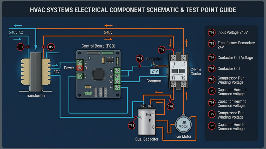
- Run capacitors remain in the motor circuit continuously during operation. They are typically oval or round in shape and maintain proper motor speed, torque, and efficiency. A dual-run capacitor combines two run capacitors in a single housing, with one section serving the compressor motor and the other serving the condenser fan motor. Dual-run capacitors have three terminals labeled C (common), HERM (compressor), and FAN.
- Start capacitors provide a temporary high-torque boost to help motors overcome inertia during startup. They are typically cylindrical with a plastic housing and are removed from the circuit by a potential relay or electronic start device once the motor reaches approximately 75% of its running speed.
Every capacitor has critical specifications that must be matched during replacement:
- Capacitance, measured in microfarads (µF), determines the amount of energy the capacitor can store. Run capacitors must be replaced within a +/- 10% tolerance of the original rating. A 45 µF capacitor, for example, should measure between 40.5 µF and 49.5 µF to be considered acceptable.
- Voltage rating indicates the maximum voltage the capacitor can safely handle. Always select a replacement with a voltage rating equal to or higher than the original. Common ratings are 370 VAC and 440 VAC. A 440 VAC capacitor can replace a 370 VAC capacitor, but not the reverse.
- Frequency rating is typically 50/60 Hz for standard AC applications in North America.
Common Capacitor Failures
- Open capacitor: The internal connection is broken. The capacitor reads zero capacitance, and the motor will hum but fail to start.
- Shorted capacitor: The dielectric has broken down completely. This often presents with a bulging or leaking case and can blow fuses or trip breakers.
- Weak capacitor: Capacitance has degraded below acceptable tolerance. The motor may start slowly, draw excessive amperage, overheat, or cycle on its overload protector.
- Physical damage: Bulging tops, oil leaks, cracked casings, or discoloration all indicate failure or imminent failure.
Troubleshooting Capacitors
Safety is non-negotiable. Before touching any capacitor, disconnect all power to the unit at the disconnect switch and the breaker panel. Then discharge the capacitor by placing a 20,000 ohm, 5-watt resistor across each set of terminals for at least 30 seconds. Verify discharge with a multimeter set to AC voltage. Capacitors can hold a lethal charge long after power is removed.
- Visual inspection: Examine the capacitor for bulging, leaking oil, cracks, or burn marks. Any of these signs warrant immediate replacement.
- Capacitance test: Set your multimeter to the capacitance (µF) setting. Place the leads on the capacitor terminals. Compare the reading to the rated value printed on the capacitor. If the reading is more than 10% below the rated value, the capacitor is weak and should be replaced. No reading indicates an open capacitor.
- Ohmmeter check (rudimentary only): Set your meter to a high ohm range. Touch the leads to the capacitor terminals. The meter should briefly show low resistance, then climb toward infinity as the capacitor charges. This confirms basic functionality but does not verify the actual capacitance value. Do not rely on this test alone.
Capacitor Replacement
Before removing the old capacitor, photograph the wiring connections. Match the replacement capacitor by capacitance value, voltage rating, and type. Secure the new capacitor in the mounting bracket, connect wires to the correct terminals, and verify all connections are tight. A loose connection on a capacitor terminal causes arcing, heat damage, and premature failure.
Common Misconceptions About Capacitors
- “A capacitor is only needed to start the motor.” Run capacitors operate continuously and are essential for motor efficiency and longevity.
- “Any capacitor with the same voltage rating will work.” The capacitance value must match within tolerance. Installing the wrong µF rating causes motor damage.
- “Bulging is the only sign of failure.” A capacitor can test weak or open with no visible external damage.
Contactors
Contactor Fundamentals
A contactor is an electrically controlled switch designed to handle high-voltage, high-current circuits. In residential and light commercial HVAC systems, contactors control power to compressors, condenser fan motors, and electric heat strips. When the thermostat calls for cooling or heating, a low-voltage signal (typically 24 VAC) energizes the contactor coil, which creates a magnetic field that pulls a set of contacts closed, completing the high-voltage circuit.
Key contactor components include:
- Coil: An electromagnetic winding rated for a specific voltage (commonly 24 VAC in residential systems, though 120 VAC and 240 VAC coils exist in commercial applications).
- Contacts: Conductive pads, typically silver-cadmium alloy, that make or break the high-voltage circuit. Most residential HVAC contactors use normally open (NO) contacts.
- Frame and armature: The mechanical structure that holds the coil and contacts, with a spring-loaded plunger that moves the contacts.
Critical specifications for replacement include coil voltage, ampere rating (the maximum current the contacts can carry, commonly 25A, 30A, or 40A for residential units), and number of poles (single-pole or double-pole).
Common Contactor Failures
- Burned or pitted contacts: Repeated arcing erodes the contact surfaces, increasing resistance and generating heat. This is the most common failure mode.
- Stuck (welded) contacts: Excessive arcing welds the contacts together, causing the compressor or fan to run continuously regardless of the thermostat signal.
- Coil failure: An open coil has no continuity and will not energize. A shorted coil draws excessive current and may blow the control transformer fuse.
- Chattering: Rapid opening and closing of contacts, often caused by low control voltage (below 20 VAC at the coil terminals) or a weak coil.
- Mechanical failure: Broken springs, cracked frames, or corroded components prevent smooth operation.
Troubleshooting Contactors
Disconnect all power before inspecting or testing a contactor.
- Visual inspection: Remove the contactor cover if possible and examine the contacts. Heavy pitting, discoloration, or material buildup on the contact surfaces indicates the contactor should be replaced. Check for loose wires on both line and load terminals.
- Coil voltage test: With power restored and the thermostat calling, measure voltage at the coil terminals. You should read the rated coil voltage (typically 24 VAC). If voltage is present but the contactor does not pull in, the coil has failed. If voltage is absent, the problem is upstream in the control circuit.
- Voltage across contacts: With the contactor energized, measure voltage across each set of load-side contacts. A good contact shows 0 volts (or very close to it). Any significant voltage reading across a closed contact indicates resistance from pitting or burning.
- Coil continuity test: With power disconnected, measure resistance across the coil terminals. A typical 24 VAC coil reads between 10 and 100 ohms. An infinite reading (OL) indicates an open coil.
- Mechanical check: With power off, use an insulated tool to press the contactor plunger manually. The contacts should move freely and snap back when released. Sticking or binding indicates mechanical failure or welded contacts.
Contactor Replacement
Match the replacement contactor by coil voltage, ampere rating, and pole configuration. Photograph all wiring before disconnecting the old unit. After installation, tighten all terminal screws to the manufacturer’s torque specifications. Loose connections are the leading cause of premature contactor failure due to arcing and heat buildup.
Common Misconceptions About Contactors
- “A contactor is just a relay.” While the operating principle is similar, contactors are built for much higher voltage and current loads than standard relays. They are not interchangeable.
- “If the coil pulls in, the contactor is good.” The coil can function perfectly while the contacts are burned, pitted, or welded.
- “Tightening the screws or filing the contacts will fix the problem.” Once contacts are significantly pitted or burned, replacement is the only reliable solution. Filing contacts removes the protective alloy coating and accelerates future failure.
Control Boards
Control Board Fundamentals
The control board (also called a circuit board or PCB) serves as the central logic hub of a modern HVAC system. It receives input signals from thermostats, sensors, and safety devices, then executes programmed sequences to operate blower motors, compressors, ignition systems, defrost cycles, and safety shutdowns. Control boards contain microprocessors, relays, terminal blocks, fuses, LED status indicators, and sometimes dip switches or potentiometers for configuration.
Common types include furnace control boards (managing ignition sequences and blower operation), air conditioner control boards (managing compressor and fan cycling), and heat pump control boards (managing reversing valve operation and defrost cycles). The increasing use of ECM (electronically commutated motor) and variable-speed blower motors has made control board designs more complex, with integrated motor control logic and communication protocols.
Common Control Board Failures
- Burned components: Power surges, lightning strikes, or sustained overcurrent conditions can burn resistors, capacitors, or traces on the board.
- Failed onboard relays: Relays that control blower motors, compressors, or other loads can fail open (component does not operate) or fail closed (component runs continuously).
- Blown fuses: Most control boards have one or more onboard fuses (typically 3A or 5A automotive-style or glass tube fuses). A blown fuse indicates an overcurrent event in the low-voltage control circuit.
- Loose or corroded connections: Vibration and moisture cause terminal block connections to degrade over time.
- Sensor-related symptoms: A failed thermistor or flame sensor can cause the board to lock out or behave erratically. The board itself may be fine, but the faulty sensor input produces incorrect responses.
Troubleshooting Control Boards
Always disconnect power before inspecting a control board.
- Visual inspection: Look for darkened or burned areas on the board, blown fuses, swollen capacitors, melted connectors, or signs of moisture intrusion. Inspect all wire connections at terminal blocks for tightness and corrosion.
- Power supply verification: With power restored, measure voltage at the board’s incoming power terminals. Most residential HVAC control boards require 24 VAC from the control transformer. Verify this voltage is within an acceptable range (24 VAC +/- 10%).
- Output voltage testing: While the system is calling for a specific function, measure voltage at the corresponding output terminal. For example, when the thermostat calls for cooling, the Y terminal on the board should output 24 VAC to energize the contactor coil. Absence of expected output voltage with correct input signals points to a board failure.
- LED diagnostic codes: Most modern furnace and heat pump control boards feature LED indicators that flash error codes. Consult the manufacturer’s service manual or the code legend typically printed on the board’s access panel door. Common codes indicate flame sense failure, pressure switch faults, limit switch trips, or communication errors.
- Fuse continuity: Remove and test onboard fuses with a multimeter set to continuity. A blown fuse must be replaced, but always identify and correct the cause of the overcurrent before restoring power. Common causes include shorted thermostat wires, failed contactors, or defective external components.
- Sensor testing: Measure resistance across temperature sensors (thermistors) and compare readings to the manufacturer’s resistance-temperature chart. A 10K ohm NTC thermistor, for example, should read approximately 10,000 ohms at 77°F (25°C). Significantly different readings indicate a failed sensor, not a failed board.
- Diagnostic modes: Some boards offer built-in diagnostic or test modes accessible through button sequences or dip switch combinations. These modes force specific outputs for testing purposes. Always refer to the manufacturer’s documentation for procedures.
Control Board Replacement
Control boards must be replaced with the exact part number or a manufacturer-approved universal replacement. Before disconnecting any wires, label every connection or take detailed photographs. Record all dip switch positions on the old board and replicate them exactly on the replacement. Some newer boards may require firmware configuration or setup through proprietary diagnostic tools. Secure the replacement board to the proper mounting standoffs to prevent grounding issues, and verify all low-voltage and line-voltage connections before restoring power.
Common Misconceptions About Control Boards
- “If the board lights up, it is working.” The power supply section can function while individual relays, output circuits, or logic components have failed.
- “All control boards are interchangeable.” Boards are specific to the equipment model and often to the serial number range. Using an incorrect board can cause equipment damage or unsafe operation.
- “You can always repair a burned component on the board.” While component-level repair is possible in some cases, it requires advanced soldering skills and electronic diagnostic capability. For most field technicians, full board replacement is more practical, reliable, and cost-effective.
- “Replacing a control board is straightforward.” Incorrect dip switch settings, misrouted wires, or failure to transfer configuration settings from the old board can cause the new board to malfunction or lock out immediately.
Related Considerations
Effective electrical troubleshooting depends on more than component knowledge. Several supporting practices improve accuracy and safety:
- Wiring diagrams: Always reference the equipment’s wiring diagram, found inside the access panel or in the service manual. The diagram shows expected voltages, wire colors, and component relationships.
- Multimeter proficiency: A quality digital multimeter capable of measuring AC/DC voltage, resistance, continuity, and capacitance is the most important tool in electrical troubleshooting. Verify your meter is rated for the voltages you are measuring (CAT III minimum for HVAC work).
- Overcurrent protection: Fuses and circuit breakers protect components from damage. A repeatedly tripping breaker or blown fuse is a symptom, not the root cause. Always investigate the underlying issue.
- Electrical safety: Follow lockout/tagout procedures, verify zero energy state before working on components, and always assume a circuit is live until proven otherwise. Adhere to all local electrical codes and regulations.
- Advanced diagnostic tools: Oscilloscopes and data loggers can capture intermittent faults and waveform anomalies that a standard multimeter cannot detect. These tools are increasingly relevant as variable-speed and communicating HVAC systems become more common.
Key Takeaways
Troubleshooting capacitors, contactors, and control boards requires a systematic approach grounded in understanding how each component functions within the larger HVAC system. Always start with safety: disconnect power, discharge capacitors, and verify zero energy before touching any component. Use visual inspection as your first diagnostic step, then confirm findings with measured electrical values. Match replacement components precisely by specification, not by appearance. Document wiring configurations before disconnecting anything. And above all, consult the manufacturer’s service documentation whenever possible. These fundamentals, practiced consistently, will produce faster and more accurate diagnoses in the field. Technicians seeking to advance their skills should pursue formal electrical training through accredited HVAC programs and stay current with evolving equipment technologies, particularly as communicating systems and variable-speed drives continue to reshape modern HVAC service work.