A homeowner installs a brand-new, top-of-the-line HVAC system, yet rooms remain stuffy in summer and drafty in winter. The culprit is almost never the equipment itself. It is the sizing. Without a proper load calculation, even premium HVAC equipment will underperform, waste energy, and fail prematurely. Manual J is the industry-standard procedure for determining exactly how much heating and cooling capacity a residential building requires. Developed by the Air Conditioning Contractors of America (ACCA) and published as the ANSI/ACCA 2 standard, Manual J is not a suggestion or a guideline. It is the recognized protocol required by most building codes across the United States. The process accounts for climate, building construction, orientation, occupancy, and dozens of other variables to produce precise heating and cooling load figures in BTU/h. While manual calculations are technically possible, practitioners almost universally rely on software such as Wrightsoft Right-Suite Universal, Elite Software RHVAC, or Carrier HAP. This article walks through the complete Manual J process, from foundational concepts to final equipment selection.
Key Concepts and Fundamentals
Heat Gain vs. Heat Loss
Every Manual J calculation revolves around two fundamental phenomena. Heat gain is the total amount of heat entering a building, which the cooling system must remove. Heat loss is the total amount of heat escaping a building, which the heating system must replace. Each of these breaks down into two components:
- Sensible heat changes the temperature of the air. Sources include sunlight streaming through windows, body heat from occupants, lighting, and electronic equipment.
- Latent heat changes the moisture content of the air without changing its temperature. Sources include people breathing and perspiring, cooking, showering, and moisture infiltrating from outdoors.
Cooling systems must handle both sensible and latent loads. Heating calculations focus primarily on sensible heat loss, since winter air typically holds less moisture.
BTU/h: The Unit of Measurement
Manual J expresses all loads in BTU/h (British Thermal Units per hour). One BTU is the energy required to raise one pound of water by one degree Fahrenheit. BTU/h measures the rate of heat transfer. For cooling, the industry also uses tons: 1 ton of cooling equals 12,000 BTU/h.
Design Temperatures
Design temperatures represent the near-extreme outdoor conditions that the HVAC system must handle. These are not averages. For cooling, the outdoor design temperature is the value exceeded only 1% of annual hours. For heating, it is the temperature that outdoor conditions fall below only 1% or 2.5% of the time. ACCA and ASHRAE publish approved climate data for locations throughout North America. Using average temperatures instead of design temperatures is one of the most common and costly errors in load calculations.
Indoor design temperatures are typically set at 70°F for heating and 75°F for cooling, though these can be adjusted based on client preference. The difference between indoor and outdoor design temperatures, known as ΔT (delta T), drives the magnitude of the load calculation.
R-Value, U-Value, and SHGC
R-value measures thermal resistance. Higher R-values mean better insulation. U-value measures thermal transmittance, or how easily heat passes through a material. The two are inversely related: U = 1/R. Manual J uses U-values in its heat transfer equations because they plug directly into the formula Q = U × A × ΔT, where Q is heat flow, A is area, and ΔT is the temperature difference.
For windows, the Solar Heat Gain Coefficient (SHGC) indicates the fraction of solar radiation admitted through the glass. A window with an SHGC of 0.25 admits 25% of incident solar energy. Lower SHGC values reduce cooling loads in hot climates.
Infiltration and Air Changes per Hour
Infiltration is uncontrolled air leakage through cracks, gaps, and penetrations in the building envelope. It is measured in Air Changes per Hour (ACH), which represents how many times the entire volume of air in a space is replaced per hour. A tight home might have 0.15 to 0.25 natural ACH, while a leaky older home could exceed 1.0 ACH. Factors influencing infiltration include wind exposure, the stack effect in multi-story buildings, and overall construction quality. A blower door test provides the most accurate measurement.
Climate Zones
The International Energy Conservation Code (IECC) divides the United States into climate zones ranging from Zone 1 (very hot) to Zone 8 (subarctic). These zones influence design temperatures, insulation requirements, and construction practices. Manual J software automatically applies the correct climate data once you enter the project location.
Step-by-Step Manual J Load Calculation Walkthrough
Step 1: Project Information
Begin by entering the project address and geographic location. The software uses this data to pull local outdoor design temperatures, altitude, latitude, and daily temperature range. You also specify building orientation, which determines how solar exposure affects each wall and window. Record applicable building code requirements, as many jurisdictions mandate compliance with specific IECC editions.
Step 2: Building Envelope Data
The building envelope is the thermal boundary separating conditioned space from the outdoors. Accurate envelope data is the backbone of every Manual J calculation.
Walls: Document each exterior wall’s construction from outside to inside: siding type, sheathing, insulation type and thickness, framing material and spacing, and interior finish. Calculate or look up the composite R-value. Record the gross wall area for each orientation, then subtract window and door openings to get the net wall area. A 2×6 wall with R-19 fiberglass batts performs very differently from a 2×4 wall with R-13, and Manual J captures this precisely.
Windows and Doors: For every window, record the size, orientation, U-value, and SHGC. Use ratings from the National Fenestration Rating Council (NFRC), which are printed on the label of every rated window. Do not confuse SHGC with Visible Transmittance (VT); VT measures light transmission, not heat. A double-pane low-e window might have a U-value of 0.30 and an SHGC of 0.25. Note shading devices such as overhangs, awnings, and interior blinds, as these significantly reduce solar heat gain. For doors, record the R-value and area.
Roof and Ceiling: If the home has an attic, the ceiling is the primary thermal boundary. Document ceiling insulation type and R-value, along with the ceiling area. Note whether the attic is ventilated or sealed. For cathedral or vaulted ceilings where insulation sits directly between rafters, record the rafter depth, insulation R-value, and roofing material. Roof color matters: a dark roof absorbs significantly more solar radiation than a light-colored or reflective roof.
Floor: The floor calculation depends on the foundation type:
- Slab-on-grade: Heat loss occurs through the slab perimeter. The calculation uses a perimeter heat loss factor (BTU/h per linear foot per degree ΔT) rather than an area-based approach.
- Crawlspace: Document whether the crawlspace is vented or sealed, insulation location (floor joists vs. crawlspace walls), and the R-value.
- Basement: Below-grade walls lose less heat than above-grade portions. Record the depth below grade, wall insulation, and floor insulation if present.
Step 3: Internal Loads
Internal loads are heat generated within the conditioned space. They add to the cooling load but offset the heating load.
People: The standard assumption is one person per bedroom plus one additional occupant. Each person generates approximately 230 BTU/h of sensible heat and 200 BTU/h of latent heat during typical residential activity.
Lighting: All electrical energy consumed by lights converts to heat. A home with 2,000 watts of lighting operating simultaneously adds roughly 6,824 BTU/h of sensible heat (watts × 3.412 = BTU/h). LED lighting produces far less heat than incandescent fixtures for the same light output.
Appliances: Refrigerators, ovens, dishwashers, computers, and televisions all generate heat. Manual J provides default values for typical residential appliance loads. A kitchen with a gas range adds both sensible and latent heat. Adjust appliance loads based on actual equipment if the home has unusual features, such as a home office with multiple computers or a home business.
Step 4: Ventilation and Infiltration
Infiltration: If blower door test data is available, enter the measured value. The test provides CFM50 (airflow at 50 Pascals of pressure), which software converts to natural infiltration rates using standard formulas. Without test data, Manual J provides infiltration estimates based on construction quality: tight, semi-tight, average, semi-loose, or loose.
Ventilation: ASHRAE Standard 62.2 establishes minimum mechanical ventilation rates for residential buildings. The formula is 0.03 CFM per square foot of floor area plus 7.5 CFM per occupant. A 2,000-square-foot home with three bedrooms (four occupants) requires a minimum of 90 CFM of outdoor air. If the home uses a Heat Recovery Ventilator (HRV) or Energy Recovery Ventilator (ERV), the recovered energy offsets a portion of the ventilation load. Factor in the rated efficiency of these devices.
Step 5: Duct Losses
Ducts located outside the conditioned space lose energy. Ducts in a 130°F attic during summer or a 35°F crawlspace in winter dramatically increase loads. Document duct location, insulation R-value (R-6 and R-8 are common), and estimated leakage. A duct blaster test provides measured leakage data. Industry estimates suggest that poorly sealed ducts can increase loads by 20% to 30%.
Step 6: Software Calculation and Report Review
Once all data is entered, the software performs thousands of calculations simultaneously. It applies heat transfer equations to every surface, factors in solar angles for each orientation, combines internal and external loads, and produces a comprehensive report. Review the output carefully. Check that design temperatures, construction assumptions, and areas match reality. Even experienced professionals occasionally enter a window size incorrectly or select the wrong insulation type from a dropdown menu.
Step 7: Interpreting the Results
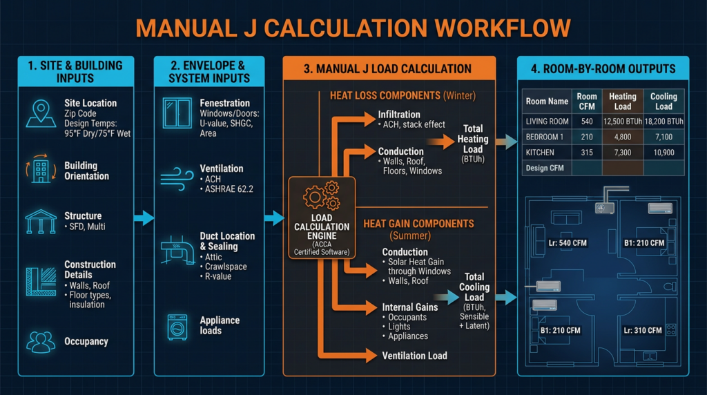
The software produces several critical outputs:
- Total cooling load (sensible plus latent), expressed in BTU/h and tons.
- Total heating load, expressed in BTU/h.
- Room-by-room load breakdown, showing individual heating and cooling loads for every room in the house.
- Sensible Heat Ratio (SHR) for cooling, which indicates the proportion of sensible load to total load. This ratio guides equipment selection to ensure adequate dehumidification.
A typical 2,000-square-foot home in a moderate climate might calculate at 30,000 BTU/h for cooling (2.5 tons) and 45,000 BTU/h for heating. These numbers vary enormously based on climate, construction quality, and building features. The room-by-room breakdown feeds directly into Manual D duct design and ensures each room receives the correct airflow.
Common Misconceptions and Mistakes
Oversizing equipment remains the most widespread problem in residential HVAC. An oversized air conditioner short cycles, running in brief bursts that cool the air but fail to remove adequate moisture. The result is a cold, clammy house with high humidity, mold risk, and inflated energy bills. An oversized furnace produces similar comfort issues. Proper Manual J sizing typically results in equipment that runs for extended periods during design conditions, which is exactly how the system should operate.
Rule-of-thumb sizing (such as 1 ton per 500 square feet or 400 square feet) ignores insulation levels, window area, orientation, climate severity, and every other variable that Manual J accounts for. Two identical floor plans built in different climates or with different insulation levels can have loads that differ by 50% or more.
Ignoring latent loads causes humidity problems in warm, humid climates. If the sensible-to-latent ratio is not properly matched to equipment capabilities, the system may control temperature while leaving indoor humidity at uncomfortable levels above 60%.
Using inaccurate data produces garbage-in, garbage-out results. Measure every wall, window, and room. Verify insulation types and thicknesses rather than assuming. Use NFRC-rated window performance data rather than generic estimates.
Neglecting duct losses leads to undersized systems that cannot maintain setpoint temperatures. Always account for duct location and condition.
Practical Applications and Benefits
A completed Manual J report serves as the foundation for the entire HVAC design process. Manual S uses the load figures to select specific equipment models that match both the sensible and latent requirements. Manual D uses the room-by-room loads to design ductwork that delivers the correct airflow to each space. Together, these three procedures form the ACCA design triad that produces efficient, comfortable, and code-compliant HVAC systems.
Beyond new construction, Manual J calculations help troubleshoot existing systems, identify opportunities for envelope improvements such as insulation upgrades or window replacements, and verify that replacement equipment is properly sized. Many equipment manufacturers require documented Manual J calculations as a condition of their warranty. Building departments increasingly require them for permits.
Related Standards and Procedures
- Manual D (Duct Design): Sizes supply and return ductwork based on room-by-room airflow requirements from Manual J.
- Manual S (Equipment Selection): Matches equipment performance data to calculated loads at design conditions.
- ASHRAE Standard 62.2: Establishes minimum ventilation rates for acceptable indoor air quality in residential buildings.
- IECC and IRC: Building codes that reference Manual J as the required load calculation method for residential HVAC design.
- Energy audits: Often include blower door testing and insulation assessment, producing data that improves Manual J accuracy.
Key Takeaways
Manual J is the only recognized standard for residential HVAC load calculations in the United States. Accurate results depend on precise measurements of the building envelope, correct design temperatures from approved climate data, and honest accounting of infiltration and internal loads. The calculation produces heating and cooling loads in BTU/h for the whole house and for each individual room. These figures drive every downstream decision, from equipment selection to duct sizing to register placement. Oversizing remains the industry’s most persistent error, and a proper Manual J calculation is the single most effective tool for preventing it. While software handles the math, the professional performing the calculation must understand what every input means and verify that every output makes sense. For complex projects or high-performance homes, consulting a qualified HVAC professional who performs full Manual J calculations is not just recommended. It is essential for delivering comfort, efficiency, and system longevity.