Proper refrigerant charge is one of the most critical factors in HVAC system performance, energy efficiency, and equipment longevity. Studies by the Department of Energy have shown that systems with incorrect charge levels can lose 5% to 20% of their cooling capacity and consume significantly more energy. Superheat and subcooling measurements are the primary diagnostic methods technicians use to verify and adjust refrigerant charge with precision. This article provides a detailed, practical guide to both methods, covering the underlying principles, step-by-step measurement procedures, interpretation of readings, and real-world troubleshooting. With the industry transitioning from legacy refrigerants like R-22 to R-410A, R-32, and emerging A2L blends such as R-454B, understanding the specific charging requirements of each refrigerant has never been more important.
Key Concepts and Refrigerant Cycle Review
The Refrigeration Cycle
Every air conditioning and refrigeration system operates on the same fundamental cycle involving four main components:
- Compressor: Compresses low-pressure, low-temperature refrigerant vapor into high-pressure, high-temperature vapor. This is the heart of the system.
- Condenser: Rejects heat from the high-pressure refrigerant vapor, causing it to condense into a high-pressure liquid.
- Metering device: Reduces the pressure and temperature of the liquid refrigerant before it enters the evaporator. Common types include fixed orifice devices (piston or capillary tube) and thermostatic expansion valves (TXVs).
- Evaporator: Absorbs heat from the conditioned space, causing the low-pressure liquid refrigerant to boil and evaporate into a vapor.
Understanding where phase changes occur in this cycle is essential for interpreting superheat and subcooling readings accurately.
Saturation Temperature and Pressure
Saturation temperature is the temperature at which a refrigerant changes phase (boils or condenses) at a given pressure. Every refrigerant has a unique, fixed relationship between saturation temperature and pressure, documented in pressure-temperature (PT) charts. For example, R-410A at 118.3 psig has a saturation temperature of approximately 40°F. Digital manifolds and smartphone apps now calculate this automatically, but every technician should understand the underlying PT relationship to diagnose system issues confidently.
Superheat Defined
Superheat is the number of degrees the refrigerant temperature rises above its saturation temperature at a given pressure, measured at the suction line near the compressor. It tells you how much heat the refrigerant vapor has absorbed after it has completely boiled in the evaporator. Superheat confirms that only vapor, not liquid, is reaching the compressor.
Subcooling Defined
Subcooling is the number of degrees the refrigerant temperature drops below its saturation temperature at a given pressure, measured at the liquid line near the condenser. It tells you how much the liquid refrigerant has been cooled after it has completely condensed. Subcooling confirms that only liquid, not a mixture of liquid and vapor, is feeding the metering device.
Why Phase Change Matters
Proper superheat ensures that the evaporator is fully utilized for heat absorption and that no liquid slugs reach the compressor, which can cause catastrophic mechanical damage. Proper subcooling ensures that the metering device receives a solid column of liquid, preventing flash gas that reduces system capacity and efficiency. Together, these two measurements give technicians a complete picture of charge status and system health.
Superheat Method: Principles and Application
Why Superheat Matters
Superheat is your primary indicator of evaporator performance and compressor protection. A compressor is designed to pump vapor, not liquid. When superheat drops too low, liquid refrigerant can wash oil from compressor bearings and damage reed valves or scroll elements. Conversely, excessively high superheat means the evaporator is starved for refrigerant, reducing cooling capacity and potentially overheating the compressor motor, which is cooled by returning suction gas.
Target Superheat Values
Target superheat varies based on several factors:
- Metering device type: Systems with a TXV (or electronic expansion valve) actively regulate refrigerant flow to maintain a relatively constant superheat, typically 8°F to 12°F at the evaporator outlet. The TXV senses suction line temperature through a sensing bulb and adjusts its opening accordingly. For fixed orifice systems (pistons or capillary tubes), target superheat is variable and depends heavily on indoor and outdoor conditions, typically ranging from 10°F to 20°F.
- Evaporator load: Higher indoor temperatures and humidity levels increase the heat load on the evaporator, which tends to raise superheat. Many manufacturers provide superheat charging charts that cross-reference indoor wet-bulb temperature with outdoor dry-bulb temperature to determine the correct target.
- Manufacturer specifications: Always consult the unit’s installation manual, service bulletin, or nameplate data. Manufacturer targets take precedence over general guidelines.
Measuring Superheat: Step by Step
- Allow the system to run for at least 10 to 15 minutes to stabilize operating conditions.
- Connect your manifold gauge set to the suction line service port (low-pressure side, near the compressor).
- Read the suction pressure and convert it to saturation temperature using a PT chart for the specific refrigerant in the system. A digital manifold will do this automatically.
- Attach a thermocouple or pipe clamp temperature sensor to the suction line at the same location as the service port. Secure it firmly with a spring clamp and insulate it with closed-cell foam to prevent ambient air from skewing the reading.
- Read the actual suction line temperature.
- Subtract the saturation temperature from the actual line temperature. The result is superheat.
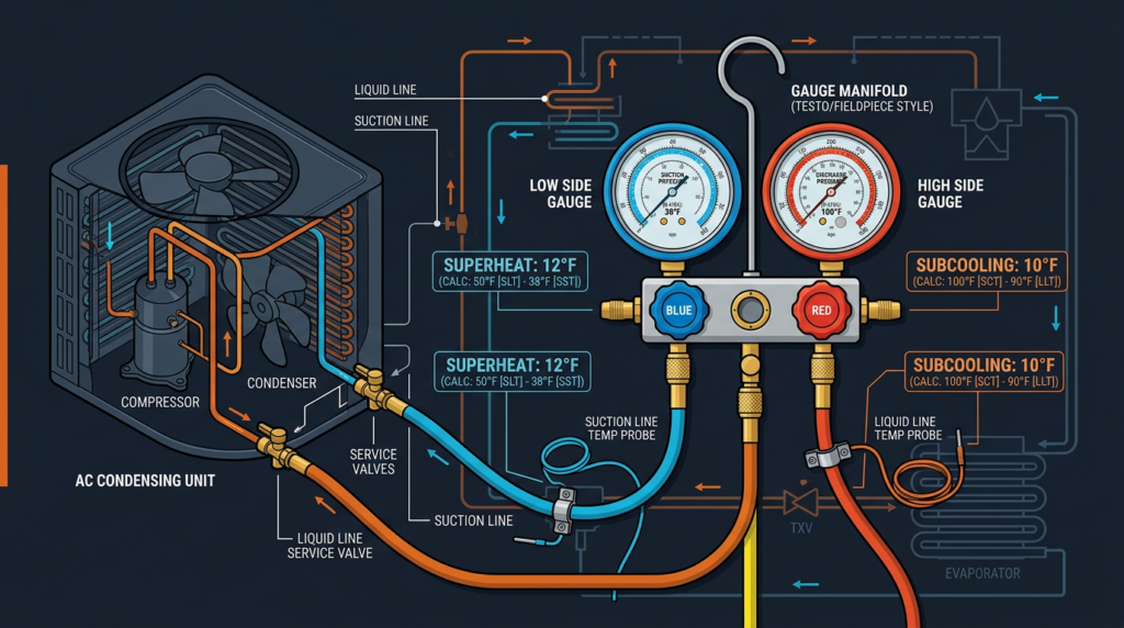
Example: Suction pressure on an R-410A system reads 118 psig. The PT chart shows a saturation temperature of approximately 40°F. The thermocouple reads 52°F on the suction line. Superheat equals 52°F minus 40°F, which is 12°F.
Interpreting Superheat Readings
High superheat (above target) can indicate:
- Refrigerant undercharge: not enough refrigerant reaching the evaporator
- Low evaporator airflow: dirty air filter, collapsed duct, iced coil, or slow blower motor
- Restricted refrigerant flow: kinked liquid line, clogged filter drier, or partially blocked metering device
- Malfunctioning metering device: TXV stuck closed or improperly adjusted
Low superheat (below target) can indicate:
- Refrigerant overcharge: excess refrigerant flooding the evaporator
- Excessive evaporator airflow: blower speed set too high for current conditions
- Malfunctioning metering device: TXV stuck open, allowing too much refrigerant through
Charging Adjustments Using Superheat
On fixed orifice systems, superheat is the primary charging method. Adding refrigerant decreases superheat; recovering refrigerant increases it. Make small adjustments (a few ounces at a time), allow the system five minutes to stabilize, and recheck. On TXV systems, superheat is primarily a diagnostic tool for valve function, not for setting charge level. If the TXV is functioning correctly, use subcooling for charge adjustment.
Subcooling Method: Principles and Application
Why Subcooling Matters
Subcooling is the preferred charging method for systems equipped with a TXV or electronic expansion valve. It tells you how much liquid refrigerant is stored in the condenser beyond what is needed for phase change. Proper subcooling ensures a solid stream of liquid reaches the metering device, preventing flash gas (premature boiling in the liquid line) that reduces system capacity and causes erratic metering device behavior.
Target Subcooling Values
- TXV systems: Target subcooling typically falls between 8°F and 12°F, though some manufacturers specify values as high as 15°F.
- Condenser airflow: Restricted airflow from a dirty condenser coil or a failing fan motor will increase head pressure and produce abnormally high subcooling readings that do not reflect true charge level. Always verify airflow before adjusting charge.
- Ambient temperature: Higher outdoor ambient temperatures increase condensing pressure, which can affect subcooling. Some manufacturers provide subcooling correction factors for extreme ambient conditions.
- Refrigerant type: Different refrigerants may have slightly different optimal subcooling ranges. Always reference manufacturer data for the specific refrigerant.
Measuring Subcooling: Step by Step
- Allow the system to run for at least 10 to 15 minutes to reach stable conditions.
- Connect your manifold gauge set to the liquid line service port (high-pressure side, near the condenser outlet).
- Read the liquid line (discharge/high-side) pressure and convert it to saturation temperature using the appropriate PT chart or digital manifold.
- Attach a thermocouple or pipe clamp temperature sensor to the liquid line at the same location. Secure and insulate the sensor.
- Read the actual liquid line temperature.
- Subtract the actual liquid line temperature from the saturation temperature. The result is subcooling.
Example: Liquid line pressure on an R-410A system reads 370 psig. The PT chart gives a saturation temperature of approximately 105°F. The thermocouple reads 95°F. Subcooling equals 105°F minus 95°F, which is 10°F.
Interpreting Subcooling Readings
High subcooling (above target) can indicate:
- Refrigerant overcharge: excess refrigerant backing up in the condenser
- Restricted liquid line: kinked tubing, clogged filter drier, or partially closed service valve
- Low condenser airflow: dirty coil, failed fan motor, or obstructed air path
Low subcooling (below target) can indicate:
- Refrigerant undercharge: not enough liquid refrigerant in the condenser
- Excessive condenser airflow (rare in typical installations)
- Non-condensable gases in the system (air contamination from improper evacuation)
Charging Adjustments Using Subcooling
Adding refrigerant increases subcooling; recovering refrigerant decreases it. As with superheat adjustments, add or remove refrigerant in small increments and allow the system to stabilize before rechecking. On TXV systems, subcooling is your primary indicator for proper charge because the TXV controls superheat independently.
Refrigerant-Specific Considerations
R-410A
R-410A operates at approximately 50% to 70% higher pressures than R-22. Technicians must use manifold gauges, hoses, and recovery equipment rated for at least 800 psig working pressure. Because R-410A is a near-azeotropic blend (50/50 mix of R-32 and R-125), it must be charged as a liquid from the tank to prevent fractionation, which would alter the blend ratio and degrade performance. Invert the charging cylinder or use a dip tube cylinder to ensure liquid delivery.
R-32
R-32 is a single-component refrigerant gaining adoption in ductless mini-splits and some unitary systems. It operates at pressures similar to R-410A but has a higher discharge temperature, requiring careful monitoring of compressor temperatures. R-32 carries an A2L flammability classification, meaning it is mildly flammable. Charging procedures require leak-free connections, proper ventilation, and compliance with local fire codes.
A2L Refrigerants (R-454B and Others)
The industry is transitioning to A2L refrigerants under EPA regulations and the AIM Act, which mandates significant GWP reductions. R-454B (marketed as Opteon XL41) is the leading R-410A replacement with a GWP of 466 compared to R-410A’s 2088. Key considerations for charging A2L refrigerants include:
- Use only equipment certified for A2L use, including electronic leak detectors rated for flammable refrigerants
- Eliminate ignition sources in the work area during charging and recovery
- R-454B is a zeotropic blend with temperature glide of approximately 1°F, so charge as a liquid
- Superheat and subcooling principles remain the same, but always use PT data specific to the refrigerant
- Technicians handling A2L refrigerants should complete updated EPA Section 608 training that covers safe handling of mildly flammable substances
Common Misconceptions and Troubleshooting Tips
Misconceptions
- “Superheat and subcooling only matter on TXV systems.” Superheat is the primary charging method for fixed orifice systems, and subcooling can still provide useful diagnostic data. Both measurements have value on all system types.
- “Target values are universal.” Target superheat and subcooling vary by manufacturer, system type, metering device, refrigerant, and operating conditions. Never assume a single number applies across all equipment.
- “Adding refrigerant fixes everything.” Incorrect charge is a symptom as often as it is a cause. Airflow problems, dirty coils, restriction, and refrigerant leaks must be identified and corrected before adjusting charge.
Essential Troubleshooting Steps
- Verify system cleanliness first: Check and clean air filters, evaporator coils, and condenser coils before connecting gauges. A dirty filter alone can shift superheat readings by 5°F to 10°F.
- Leak check before charging: Pressure test the system with dry nitrogen and use an electronic leak detector to locate and repair leaks before adding any refrigerant.
- Verify proper airflow: Measure supply and return temperatures. A typical cooling system should produce a temperature split of 14°F to 22°F across the evaporator coil. Use an anemometer or static pressure gauge to verify airflow is within manufacturer specifications.
- Proper evacuation: Pull a vacuum to at least 500 microns and hold for 10 minutes to confirm no leaks and removal of moisture and non-condensables before charging.
- Calibrate instruments regularly: Gauges and thermocouples drift over time. Verify accuracy at least annually against known standards.
- Insulate temperature sensors: A thermocouple exposed to ambient air will give inaccurate readings. Always use pipe insulation or foam tape over the sensor.
- Use both measurements together: Checking both superheat and subcooling gives a more complete diagnostic picture and helps distinguish charge issues from airflow or restriction problems.
- Document everything: Record pressures, temperatures, superheat, subcooling, ambient conditions, refrigerant added or removed, and any repairs. This data is invaluable for future service calls.
Practical Scenarios
Scenario 1: Undercharged R-410A System with TXV
A residential split system is not cooling adequately. The technician measures 18°F superheat and 4°F subcooling. The manufacturer specifies 10°F superheat and 10°F subcooling. The low subcooling confirms an undercharge. After leak testing and finding a small leak at a flare fitting, the technician repairs the connection, evacuates the system, and charges by weight, then fine-tunes using subcooling. After adding refrigerant, subcooling reaches 10°F and superheat settles at 11°F, confirming proper charge.
Scenario 2: Overcharged System with Fixed Orifice
An older R-22 system shows 5°F superheat, well below the target of 15°F per the manufacturer’s charging chart for current conditions. Head pressure is elevated at 295 psig (normally around 260 psig). The low superheat indicates overcharge. The technician recovers refrigerant in small increments until superheat reaches 15°F and head pressure returns to normal range.
Scenario 3: Dirty Condenser Coil Mimicking Overcharge
An R-410A system shows 18°F subcooling and elevated head pressure of 430 psig. Before recovering refrigerant, the technician inspects the condenser and finds heavy debris buildup. After cleaning the coil, subcooling drops to 11°F and head pressure falls to 380 psig, both within normal range. No refrigerant adjustment was needed.
Typical Target Values Reference
The following values serve as general guidelines. Always prioritize manufacturer specifications:
- TXV systems, superheat: 8°F to 12°F at the evaporator outlet
- TXV systems, subcooling: 8°F to 12°F at the condenser outlet (some manufacturers specify up to 15°F)
- Fixed orifice systems, superheat: 10°F to 20°F (use manufacturer charging chart cross-referencing indoor wet-bulb and outdoor dry-bulb temperatures)
- Fixed orifice systems, subcooling: Used as a diagnostic reference, not as the primary charging indicator
Common Refrigerant Properties
- R-22: ODP 0.055, GWP 1810, Class A1 (non-flammable), phased out under the Montreal Protocol
- R-410A: ODP 0, GWP 2088, Class A1, being phased down under the AIM Act
- R-32: ODP 0, GWP 675, Class A2L (mildly flammable)
- R-454B: ODP 0, GWP 466, Class A2L (mildly flammable), leading R-410A replacement
Related Topics and Further Learning
- Refrigerant leak detection and repair: EPA Section 608 regulations require technicians to follow specific leak repair timelines and reporting requirements for systems containing 50 pounds or more of refrigerant.
- System performance testing: Beyond superheat and subcooling, measure static pressure, airflow (CFM), temperature split, and compressor amperage for a complete system evaluation.
- Training and certification: Organizations such as ACCA (Air Conditioning Contractors of America), RSES (Refrigeration Service Engineers Society), and NATE (North American Technician Excellence) offer training programs and certifications that keep technicians current with evolving best practices and refrigerant regulations.
- Digital tools: Invest in a quality digital manifold with Bluetooth connectivity and a smartphone app. Modern tools calculate superheat, subcooling, and target values in real time, reducing errors and speeding up the diagnostic process.
Key Takeaways
Accurate refrigerant charging through superheat and subcooling measurement is a foundational skill for every HVAC technician. Superheat protects the compressor and gauges evaporator performance, making it the primary charging method for fixed orifice systems. Subcooling confirms proper liquid delivery to the metering device and serves as the primary charging indicator for TXV systems. Always verify system cleanliness, airflow, and leak integrity before adjusting charge. Use manufacturer specifications as your target, not rules of thumb. As the industry shifts to A2L refrigerants like R-454B, technicians must stay current on new safety requirements, equipment ratings, and charging procedures. Precise refrigerant management improves system efficiency, reduces energy costs, extends equipment life, and minimizes environmental impact. Apply these principles consistently on every service call, document your work thoroughly, and invest in ongoing education to keep your skills sharp.